Table of Contents
Advertisement
Quick Links
Advertisement
Table of Contents

Related Manuals for IPS Controllers M920CA


Summary of Contents for IPS Controllers M920CA
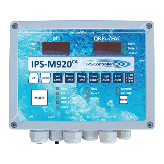
- Page 1 M920 & M920W pH/Dual ORP Controller Owner’s Manual...
-
Page 3: Table Of Contents
M920 & M920W pH/Dual ORP Controller Owner’s Manual Table of Contents I. Introducti on A. Water Chemistry B. IMPORTANT SAFETY INSTRUCTIONS C. System Components D. Specifi cati ons E. Controller Panel Descripti ons F. Electrical Descripti ons II. Installati on A. -
Page 4: Introduction
M920 & M920W pH/Dual ORP Controller Owner’s Manual I. Introduction A. Water Chemistry Water chemistry is a complex science that contains many variables. These variables not only affect the water environment itself, but they can have adverse effects on your equipment as well as your health. These are only some of the factors which we follow closely to ensure the most healthy water interactions: pH is the measurement of the acidity or basicity in an aqueous solution. -
Page 5: Important Safety Instructions
M920 & M920W pH/Dual ORP Controller Owner’s Manual IMPORTANT SAFETY INSTRUCTIONS READ AND FOLLOW ALL INSTRUCTIONS. 2. Risk of electric shock: Connect the controller to a dedicated ground- fault circuit interrupter (GFCI) circuit breaker. a. A green colored terminal or a terminal marked G, GR, Ground, Grounding, or the symbol* is located inside the supply terminal box or compartment. -
Page 6: System Components
9. CYA Cal – Cyanuric Acid Calibration/Entry d. Displays the calculated Free Available Chlorine (FAC) in parts per million (PPM) when connected to the IPS Controllers monitoring website. The ORP / FAC display will alternate between the current ORP and the last calculated FAC. FAC (PPM) calculation is not certified to NSF 50. - Page 7 (flow light should turn off). 3. pH and ORP Sensors a. pH Sensor – standard (Use only IPS Controllers part # SXPH to maintain NSF Certification) b. ORP Platinum Sensor – standard (Use only IPS Controllers part # SXORP to maintain NSF Certification) c.
- Page 8 M920 & M920W pH/Dual ORP Controller Owner’s Manual...
-
Page 9: Specifications
M920 & M920W pH/Dual ORP Controller Owner’s Manual D. Specifications Enclosure: 7.95”L x 5.98”W x 3.54”D Electrical Input/Output: 120/240 VAC, 50 - 60 Hz ORP Set Level: 400 mV to 900 mV pH Set Level: 7.0 to 8.0 Dose Time: Off, Continuous, or Timed cycle Delay Time: 1 - 99 minutes Over Timer: Off, 20-100 timed cycles, or 20-180 continuous minutes, default of 60... -
Page 10: Controller Panel Descripti Ons
M920 & M920W pH/Dual ORP Controller Owner’s Manual Flow Cell Connec�ons Accessory Flow Switch ORP1 Temp Power Sensor ORP2 Controller Communication digital display Electrical Connec�ons pushbutton LEDs Figure 2: M920 Controller Components Connecti ons E. Controller Panel Descripti ons 1. Digital Displays and Functi on LEDs a. - Page 11 M920 & M920W pH/Dual ORP Controller Owner’s Manual 2. Mode - pushbutton adjustments a. Auto - red LED b. pH standby - green LED c. ORP1 standby - yellow LED d. ORP2 standby - yellow LED e. Temp display & calibrate - green LED f.
-
Page 12: Electrical Descriptions
M920 & M920W pH/Dual ORP Controller Owner’s Manual g. Tank 1 - from tank level switch (optional) h. Tank 2 - from tank level switch (optional) i. External audible/visible alarm (optional) j. pH sensor - BNC connection k. ORP sensor - BNC connection l. -
Page 13: Installation
M920 & M920W pH/Dual ORP Controller Owner’s Manual II. Installation A. Setup (Installation video available at ipscontrollers.com) 1. Turn off all peripheral equipment such as heaters, chemical feeders, and pumps. 2. Relieve pressure from the filtration system. B. Tools 1. Cordless drill 2. 1/4” NPT Tap 3. - Page 14 M920 & M920W pH/Dual ORP Controller Owner’s Manual d. Drill a 7/16” hole and tap a 1/4” NPT port to a location down- stream from the filter and upstream from the heater and any chemical introduction points. Install a tubing connector and flex tubing to be connected to the left side flow cell port containing the flow switch.
- Page 15 M920 when the circulation pump is running. e. Method 2: Connect the AC power cord to a GFCI power source, or separately purchased IPS Controllers PressureSwitch (part # PS100). Connect the pH sensor connector to the corresponding lower port (labeled pH) at the right edge of the controller.
- Page 16 M920 & M920W pH/Dual ORP Controller Owner’s Manual Figure 4: HD2 Jumper 8. Converti ng from Cord to Permanent Connecti on a. Remove cover. b. Loosen strain relief gland from AC cord. c. Using a 3/32” (2.44mm) slot screw driver, carefully loosen terminals that att ach the AC cord to the controller box.
-
Page 17: Connection Requirements For Remote Monitoring
The remote monitoring module is programmed to “wake up” at a customer-determined interval (minutes) to send all current readings, settings, and alerts to IPS Controllers’ remote monitoring website. Because the data is being sent to the website rather than the website pulling the data from the module, the port is not left open and a static IP Address is not needed. - Page 18 The remote module is programmed to “wake up” at a customer determined interval (minutes) and send all current readings, settings, and alerts to the IPS Controllers remote monitoring website. Because the data is being sent to the website rather than the website pulling the data from the module, the port is not left open and a static IP Address is not needed.
-
Page 19: Operation
M920 & M920W pH/Dual ORP Controller Owner’s Manual III. Operation A. Overview The M920 compares the readings received from the Ph and ORP sensors to the Set Levels entered for Ph, ORP1, and ORP2. If the readings are too low or too high, the controller will turn on the feed devices for the Dose Time entered during set up. -
Page 20: Modes And Adjustments
M920 & M920W pH/Dual ORP Controller Owner’s Manual g. While still in the pH standby mode, press the pH Cal pushbutton to calibrate the reading to the value observed through the manual testing of the water. Note: Always calibrate using water from the sample port of the flow cell. h. Press the Mode pushbutton momentarily to place the controller in ORP1 standby mode. - Page 21 M920 & M920W pH/Dual ORP Controller Owner’s Manual d. The red function LED next to Auto is illuminated. e. pH and ORP digital displays monitor the sensor input levels. 2. pH standby Note: While in this mode, the green pH standby LED will illuminate, both the pH and ORP digital displays will show dashes, and all Auto functions will be disabled. When a function pushbutton is pressed, the corresponding digital display will show the function. Use the Up or Down arrow buttons to the left to increase or decrease the function value. a. Set Level 1.
- Page 22 M920 & M920W pH/Dual ORP Controller Owner’s Manual 2. The Over Timer is interlocked with the Dose Time selection. i. If the Dose Time is set to a timed cycle, the Over Timer will count timed feed cycles. Every time the set level is reached the time will reset its count.
- Page 23 M920 & M920W pH/Dual ORP Controller Owner’s Manual g. pH Cal 1. Use to adjust pH to manually tested value. 2. Maximum increase/decrease is 0.9 pH within the 6.0 to 8.4 display window. 3. ORP1 standby Note: While in this mode, the yellow ORP1 standby LED will illuminate, both the pH and ORP digital displays will show dashes, and all Auto functions will be disabled. Use the Up or Down arrow buttons to the left to increase or decrease the function value. a.
- Page 24 M920 & M920W pH/Dual ORP Controller Owner’s Manual i. If the Dose Time is set to a timed cycle, the Over Timer will count timed feed cycles. Every time the set level is reached the Over Timer will reset the count. If the set (default is 60 cycles) Over Timer cycle is reached, the ORP digital display will flash, and the ORP output relay will de- energize.
- Page 25 M920 & M920W pH/Dual ORP Controller Owner’s Manual 3. Value is calculated using pH, ORP, Temp, and CYA. *FAC (PPM) calculation is not certified to NSF 50. 4. ORP2 standby Note: While in this mode, the yellow ORP2 standby LED will illuminate, both the pH and ORP digital displays will show dashes, and all Auto functions will be disabled. Use the Up or Down arrow buttons to the left to increase or decrease the function value. a. Set Level 1. Default: 640 mV 2.
- Page 26 M920 & M920W pH/Dual ORP Controller Owner’s Manual 3. If the Dose Timer is set to a timed cycle, the Over Timer will count timed feed cycles. Every time the set level is reached the Over Timer will reset the count. If the set (default is 60 cycles) Over Timer cycle is reached, the ORP digital display will flash, and the ORP output relay will de-energize.
- Page 27 M920 & M920W pH/Dual ORP Controller Owner’s Manual Figure 5: Flow Switch Terminal c. Prior to installation, the controller operation can be tested by tilting the populated mounting board until the controller’s green light turns on (flow switch magnet at the switch’s top). Figure 6: Hidden button 7.
-
Page 28: Maintenance
M920 & M920W pH/Dual ORP Controller Owner’s Manual 8. Factory defaults To return the controller to the factory defaults: a. Place the controller in Standby Mode. b. Turn off the controller by holding down the Mode button. c. Press and hold both the Set Level and pH Cal pushbuttons, and then press the Mode button. - Page 29 M920 & M920W pH/Dual ORP Controller Owner’s Manual b. Turn off the M920 controller. c. Close the right and left valves at the bottom of the flow cell. d. Loosen the nut fitting on the sensor and gently remove it from the flow cell.
-
Page 30: Smart Phone Wi-Fi Setup
M920 & M920W pH/Dual ORP Controller Owner’s Manual IV. IPS-M920W Wi-Fi Setup A. Smart Phone Wi-Fi Setup 1. Turn on the IPS-M920W 2. Search for available Wi-Fi networks. See Figure 7. 3. Select XPicoWiFi_XXXXXX to connect. Figure 7: Available WiFi networks Note: XXXXXX indicates the last six characters of the MAC/Serial # located on the XPicoWifi device, on... - Page 31 M920 & M920W pH/Dual ORP Controller Owner’s Manual 7. The XPico WiFi main page will open. Click on Quick Connect at the top of the menu and select the WiFi network to be used (e.g. H88d3). See Figure 11. 8. Type in the Network Key associated with the selected Wi-Fi network.
-
Page 32: Desktop/Laptop Wi-Fi Setup
M920 & M920W pH/Dual ORP Controller Owner’s Manual B. Desktop/Laptop Wi-Fi Setup 1. Turn on the IPS-M920W 2. Search for available Wi-Fi networks. Figure 14: XpicoWiFi Connection 3. Select XPicoWiFi_XXXXXX to connect. See Figure 14. Note: XXXXXX indicates the last six characters of the MAC/Serial # located on the XPicoWifi device, on a label near the antenna and on the Figure 15: Network Security Password... - Page 33 M920 & M920W pH/Dual ORP Controller Owner’s Manual 8. Type in the Network Key associated with the selected Wi-Fi network. Note: Keys are case sensitive. Click on the Submit button. See Figure 19. 9. Click on the OK button in the dialog box.
-
Page 34: Troubleshooting
M920 & M920W pH/Dual ORP Controller Owner’s Manual V. Troubleshooting A. pH level too low or Alert Led On 1. pH Set level is too low: Check pH level with test kit and adjust as necessary. 2. Chemical dose time too high: Lower dose time. 3. Chemical feeder is empty (base): Refill the feeder. 4. - Page 35 M920 & M920W pH/Dual ORP Controller Owner’s Manual 3. Controller undershooting set level: 1) Check for proper valve posi- tions and leaks in chlorine lines, or 2) Increase dosing time if using timed feed, or switch to continuous feed if using a salt chlorine generator.
- Page 36 M920 & M920W pH/Dual ORP Controller Owner’s Manual F. Feeder not operating 1. No Flow: Flow light LED must be on. 2. Inadequate Flow: Check flow through the flow cell and controller. 3. Blown output fuse in the controller: Replace fuse. G. Flow LED off 1. Verify that all appropriate valves are open. 2.
-
Page 37: Warranty
Claims All warranty claims should be directed to IPS Controllers. After receiving a Returned Merchandise Authorization (RMA) number, all product must be returned (shipping prepaid) to the factory for evaluation. - Page 38 Factory Contact: 30826 Wealth Street, Murrieta, CA 92563 phone. 877-693-6903, fax. 951-693-3224 www.ipscontrollers.com M920CAOM 08/22...
Need help?
Do you have a question about the M920CA and is the answer not in the manual?
Questions and answers