Watts 994 Series Installation, Maintenance & Repair
Hide thumbs
Also See for 994 Series:
- Installation instructions (2 pages) ,
- Installation instructions manual (36 pages) ,
- Operation, installation, maintenance and repair manual (36 pages)
Advertisement
Installation, Maintenance, & Repair
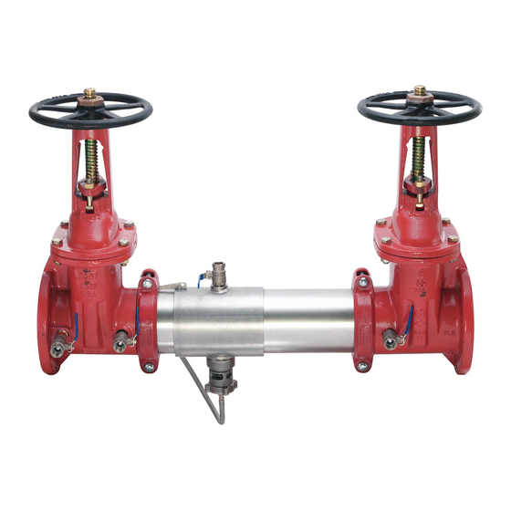
Series 994/994RPDA
Reduced Pressure Zone Assemblies
Reduced Pressure Detector Assemblies
Sizes: 2
⁄
" – 10" (65 – 250mm)
1
2
WA R NI N G
!
Read this Manual BEFORE using this equipment.
Failure to read and follow all safety and use information
can result in death, serious personal injury, property
damage, or damage to the equipment.
Keep this Manual for future reference.
Local building or plumbing codes may require modifications to the
information provided. You are required to consult the local building and
plumbing codes prior to installation. If this information is not consistent
with local building or plumbing codes, the local codes should be fol-
lowed.
Need for Periodic Inspection/Maintenance: This product must be
tested periodically in compliance with local codes, but at least once per
year or more as service conditions warrant. Corrosive water conditions,
and/or unauthorized adjustments or repair could render the product
ineffective for the service intended. Regular checking and cleaning of the
product's internal components helps assure maximum life and proper
product function.
NOTICE
Inquire with governing authorities for local installation requirements
NOTICE
For Australia and New Zealand: Pipeline strainers should be installed
between the upstream shutoff valve and the inlet of the backflow
preventer.
Testing
For field testing procedure, refer to Watts installation sheets
IS-TK-DP/DL, IS-TK-9A, IS-TK-99E and IS-TK-99D found on
www.watts.com.
For troubleshooting guide, refer to literature S-TSG.
For other repair kits and service parts, refer to our Backflow Preven-
tion Products Repair Kits & Service Parts price list PL-RP-BPD
found on www.watts.com.
For technical assistance, contact your local Watts representative.
RP/IS-994/994RPDA
994
Advertisement
Table of Contents

Related Manuals for Watts 994 Series


Summary of Contents for Watts 994 Series
- Page 1 For Australia and New Zealand: Pipeline strainers should be installed between the upstream shutoff valve and the inlet of the backflow preventer. Testing For field testing procedure, refer to Watts installation sheets IS-TK-DP/DL, IS-TK-9A, IS-TK-99E and IS-TK-99D found on www.watts.com. For troubleshooting guide, refer to literature S-TSG.
-
Page 2: Basic Installation Instructions
5. Normal discharge and nuisance spitting are ac com mo dat ed by Figure 1 the use of a Watts air gap fitting and a fabricated indirect waste Typical FlOw RaTES aS line. Floor drains of the same size MUST be provided in case of... -
Page 3: Installation
Local Codes F. The installation of a Watts air gap with the drain line ter mi nat ing above a floor drain will handle any normal dis charge or nuisance spit ting through the relief valve. How ev er, floor drain size may need to be de signed to pre vent water damage caused by a cat a- stroph ic fail ure con di tion. - Page 4 Servicing First and Second Checks Series 994/994RPDA 4" and 6" (100 – 150mm) Removing Check Assemblies (Before servicing Figure 3 be sure shutoff valves are closed) #1 Check 2 ⁄ " – 6" (65 – 150mm) Spring 1. Slowly open all ball valves to relieve air and water pressure. Loosen bolts on groove coupler and remove groove couple Cam Arm O-ring Seal &...
- Page 5 Servicing First and DANGER Second Checks Use extreme caution when servicing the first check! Servicing the Series 994/994RPDA 8" and 10" (200 – 250mm) First Check Removing Check Assemblies (Before servicing To inspect the seat and clean the seat and be certain shutoff valves are closed) clapper washer: 1.
-
Page 6: Relief Valve Disassembly
Servicing the Relief Valve 1. The relief valve may be serviced while on or off the backflow 8. Position the bottom flange cover on the bottom of the relief valve preventer valve. body and secure by hand tightening the four bottom bolts. 9. - Page 7 United States for testing Backflow Preventers. The following procedure is not a specific recommendation. The Watts series of test kits are capable of performing any of the recog- nized Backflow test procedures. A. Open TC #4 and flush test cocks No’s. 1, 2 and 3 on BF assem- bly, then close TC #4.
-
Page 8: Troubleshooting Guide
For more information: www.watts.com/prop65 limited warranty: Watts Regulator Co. (the “Company”) warrants each product to be free from defects in material and workmanship under normal usage for a period of one year from the date of original shipment. In the event of such defects within the warranty period, the Company will, at its option, replace or recondition the product without charge.
Need help?
Do you have a question about the 994 Series and is the answer not in the manual?
Questions and answers