
Related Manuals for Sakura SXAO-110HAS

Summary of Contents for Sakura SXAO-110HAS
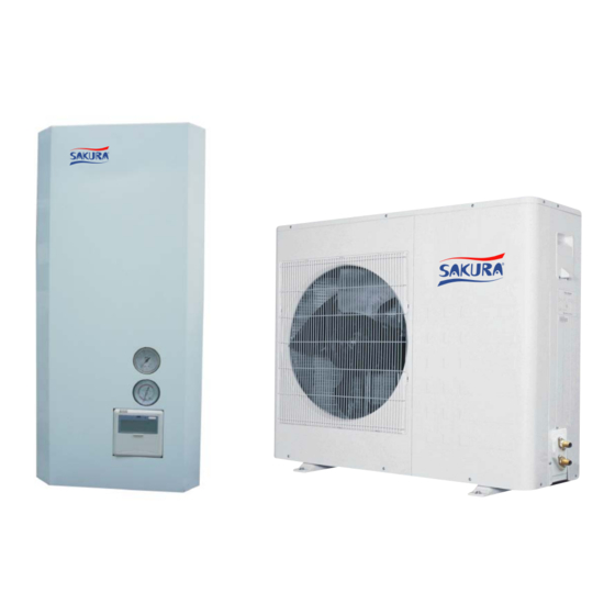
- Page 1 All in one Air to Water Heat Pump Split system Models: SXAO-110HAS SXAO-140HAS SXAO-160HAS/3 Installation and Service Manual (Please read the manual thoroughly before operation. )
-
Page 2: Table Of Contents
CONTENTS INTRODUCTION...........………..………………..2 PARTS AND DESCRIPTIONS……………………………………….…….…….3 Indoor unit- all models (External)………………………………………………………….….3 Indoor unit- all models (Internal)………………………………………………………….…..4 Outdoor unit (External): SXAO-110HAS and SXAO-140HAS………………………...…5 Outdoor unit (External): SXAO-110HAS and SXAO-140HAS………………….…..……7 Outdoor unit (External): SXAO-160HAS/3………………………………………………...8 Outdoor unit (External): SXAO-160HAS/3…………………………………………….…..9 SERVICE SPACE………………………………………………………………..10 OPERATING THE UNIT…………………………………………………….……11 Introduction………………………………………………………………………………….….11... -
Page 3: Introduction
INTRODUCTION This manual This manual describes how to start up and switch off the unit, set parameters and configure the schedule timer by means of the controller, maintain the unit and solve operational problems. This unit All in one split system consists two parts: Indoor unit and Outdoor unit. They are connected via refrigerant pipes. -
Page 4: Parts And Descriptions
PARTS AND DESCRIPTIONS Indoor unit- all models (External) -
Page 5: Indoor Unit- All Models (Internal)
Indoor unit- all models (Internal) 1. Air purge valve Remaining air in the water circuit will be automatically removed via the air purge valve. 2. Backup heater vessel The backup heater heats the water in the backup heater vessel. 3. Backup heater The backup heater consists of an electrical heating element that will provide additional heating capacity to the water circuit if the... - Page 6 The switch box contains the main electronic and electrical parts of the indoor unit. 11. Refrigerant liquid connection 12. Refrigerant gas connection 13. Water outlet connection (hot water) 14. Water inlet connection (hot water) 15. Water outlet connection (space heating/cooling water) 16.
-
Page 7: Outdoor Unit (External): Sxao-110Has And Sxao-140Has
Outdoor unit (External): SXAO-110HAS and SXAO-140HAS... - Page 8 Outdoor unit (Internal): SXAO-110HAS and SXAO-140HAS 1. Right front plate 2. Front plate 3. Air outlet grills 4. Outdoor fan 5. Fan motor 6. Fan motor holder 7. Condenser 8. Left plate 9. Top plate 10. Separated plate 11. Back grill 12.
-
Page 9: Outdoor Unit (External): Sxao-160Has/3
Outdoor unit (External): SXAO-160HAS/3... - Page 10 Outdoor unit (Internal) - SXAO-160HAS/3 1. Right front plate 2. Hand holder 3. Air outlet grills 4. Front plate 5. Outdoor fan 6. Fan motor 7. Left plate 8. Condenser 9. Fan motor holder 10. Top plate 11. Back grill 12.
-
Page 11: Service Space
SERVICE SPACE Below you will find the minimum space required to be able to complete service and maintenance tasks on the units. Indoor unit Outdoor unit... -
Page 12: Operating The Unit
OPERATING THE UNIT INTRODUCTION The heat pump system is designed to provide you a comfortable indoor climate for many years at low energy consumption. To get the most comfort with the lowest energy consumption out of your system, it is very important to observe the items listed below. -
Page 13: Features And Functions
Features and functions The digital controller is a state of the art controller that offers full control over your installation. It can control a cooling/heating and a heating only installation. Both installations are available in multiple versions which vary in capacity, electrical supply and installed equipment (backup heater in the indoor unit or domestic hot water tank with a booster heater). -
Page 14: Name And Function Of Buttons
Name and function of buttons 1. OPERATION LED The operating LED is lit during space cooling or space heating operation. The LED blinks in 1Hz frequency if a malfunction occurs. When the LED is OFF, space cooling or space heating is inactive while the other operation modes can still be active. - Page 15 8. TIME/TIMER OFF ADJUST BUTTON This multi-purpose button is used to adjust the time, the day of the week and also used in timer on function. 9. TEMPERATURE ADJUST BUTTON This multi-purpose button is used to adjust the current set point of the cooling/heating water temperature. Press this button once, the temperature increases 1℃.
-
Page 16: Name And Function Of Lcd Icons
Name and function of LCD icons 14 15 16 17 1. SPACE COOLING/HEATING SET TEMPERATURE DISPLAY The display shows the current set temperature of the space cooling/heating. If any malfunction occurs, this section will display the relating error code. 2&3&5. OPERATION MODE ICONS These icons indicate the current operation modes: space heating , space cooling , or domestic water... -
Page 17: Setting Up The Controller
The icon indicates that the ON action is selected when programming the schedule timer. The icon indicates that the OFF action is selected when programming the schedule timer. 9. CLOCK DISPLAY The clock display shows the current time. When reading or programming the schedule timer, the clock display shows the action time. 10. -
Page 18: Setting The Clock And The Day Of The Week
After initial installation, the user can set the clock and day of the week. The controller is equipped with a schedule timer that enables the user to schedule operations. Setting the clock and day of the week is required to be able to use the schedule timer. Setting the clock and the day of the week Press the button. -
Page 19: Space Heating Operation
Space heating operation ( In this mode, heating will be activated as required by the water temperature set point. The set point can be set manually. Defrost ( In space heating operation or domestic water heating operation, freezing of the outdoor heat exchanger may occur due to low outdoor temperature. -
Page 20: Schedule Timer Operation
is not available on your installation. In that case the controller will give the alarm sound and no any action will effect on the unit. Switching on and setting space cooling ( ) and heating ( 1. Use the button to select space cooling or space heating. Icon appears on the display as well as the corresponding water temperature set point. - Page 21 the user can temporarily overrule the last executed programmed command by manual operation. The schedule timer will regain control over the installation as soon as the next programmed command of the schedule timer occurs. The schedule timer is enabled ( icon displayed) or (disabled ( icon not displayed).
-
Page 22: Programming And Consulting The Schedule Timer
programmed command and will remain active until the “next” programmed command occurs. Example: imagine the actual time is 17:30 and actions are programmed at 13:00, 16:00 and 19:00. The “last” programmed command (16:00) overruled the “previous” programmed command (13:00) and will remain active until the “next” programmed command (19:00) occurs. So in order to know the actual setting, one should consult the last programmed command. -
Page 23: Programming
cooling (by means of the button), the operation mode will from then on remain cooling set points. Returning to heating mode needs to be carried out manually (by means of the button). · When the schedule timer is active in cooling mode, and the mode is changed manually to heating (by means of the button), the operation mode will from then on remain heating set points. - Page 24 selected action number. 10 Use the button to set the correct action ON time, meantime the icon is appeared. Press the button and then press the button to set the hour (from 00:00 to 23:00). Press the button and then press the button to set the minute (from 00 to 50, interval 10 minutes).
- Page 25 Press the button and then press the button to set the minute (from 00 to 50, interval 10 minutes). Press the button to save the setting. 6. Use the button to set the correct action OFF time, meantime the icon is appeared.
-
Page 26: Wiring Diagram
WIRING DIRGRAM All models- Indoor... - Page 27 SXAO-11HAS and SXAO-14HAS- Outdoor...
- Page 28 SXAO-160HAS/3- Outdoor...
-
Page 29: Digital Switch And Detailed Description
DIGITAL SWITCH AND DETAILED DESCRIPTION Digital switch introduction Digital Switch Introductions-Indoor PCB: OFF( ( Default) ) SW 1 TS In Force TS Not In Force (Wire controller In Force) SW 2 Self-check, Fast Check Normal Condition SW 3 Without Water Tank With Water Tank SW 4 Space heating/cooling Priority... -
Page 30: Maintenance
Voltage-Water temperature table Signal (Input Setting water outlet temp. Signal (Input Voltage) Setting water outlet temp. Voltage) Waiting 0.5V 5.5V 22° C 42° C 1.0V 24° C 6.0V 44° C 1.5V 26° C 6.5V 46° C 2.0V 28° C 7.0V 48°... -
Page 31: Troubleshooting
TROUBLESHOOTING The guidelines below might help to solve your problem. If you cannot solve the problem, consult your installer. No readings on the remote controller (blank display). Check if the mains power is still connected to your installation. One of the error codes appears, consult your local dealer. The schedule timer does work but the programmed actions are executed at the wrong time (e.g.
Need help?
Do you have a question about the SXAO-110HAS and is the answer not in the manual?
Questions and answers