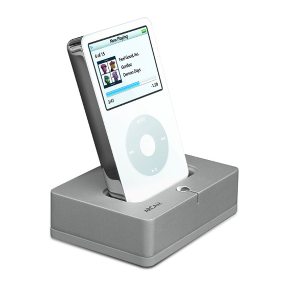
Table of Contents
Advertisement
Quick Links
S
M
ERVICE
ANUAL
iPod Dock
CONTENTS
Page
SPECIFICATION .................................................................................................................. 2
DISASSEMBLY INSTRUCTIONS ........................................................................................ 6
BLOCK DIAGRAM................................................................................................................ 7
PCB LAYOUT ....................................................................................................................... 8
SCHEMATIC DIAGRAM..................................................................................................... 10
IC BLOCK DIAGRAM......................................................................................................... 13
ELECTRICAL PARTS LIST ................................................................................................ 15
EXPLODED VIEW • PARTS LIST...................................................................................... 18
Advertisement
Table of Contents

Summary of Contents for Arcam rDock
-
Page 1: Table Of Contents
ERVICE ANUAL iPod Dock CONTENTS Page SPECIFICATION ........................2 FRONT PANEL & REAR PANEL..................5 DISASSEMBLY INSTRUCTIONS ..................6 BLOCK DIAGRAM........................ 7 PCB LAYOUT ........................8 SCHEMATIC DIAGRAM..................... 10 IC BLOCK DIAGRAM......................13 ELECTRICAL PARTS LIST ....................15 EXPLODED VIEW • PARTS LIST..................18... -
Page 2: Specification
SPECIFICATION TEST CONDITIONS Unless otherwise specified, the specification follow the testing method according to ANSI-IEEE STANDARD 185(1975), i.e. IHF-2-202 for audio section. All measurements are taken at AC and room temperature 24 º ± 4 ºC. Load resistance 47Kohm. GENERAL ITEMS Destination Europe 240V - 50 Hz +/-15% 120V - 60Hz +/-15%... - Page 3 + / - 8KV, 330 ohm, 150pF for air contact 1.6. RS232 connection with Solo One Box/Mini Solo This cable is actually used for the communication of rDock (iPod is here) with all Arcam Solo models. Test equipment: a. Cable 1000+/-20 b.
- Page 4 - Press “Connect” - Press “Test” - “Test Ok!” will be shown to indicate the success of the test - Otherwise, nothing is shown. - Disconnect the unit - 4 -...
-
Page 5: Front Panel & Rear Panel
FRONT PANEL & REAR PANEL 1. FRONT PANEL CHARGING indicator CHARGING switch 2. REAR PANEL DC IN S-VIDEO CONTROL VID OUT LEFT RIGHT +15V, 0.65A DC IN socket S-VIDEO OUT socket S-VIDEO OUT socket AUDIO OUT socket CONTROL connector - 5 -... -
Page 6: Disassembly Instructions
DISASSEMBLY INSTRUCTIONS 1. Remove screws ( 1 to 4 ) from the bottom side. Refer to Figure No.1. Figure No.1 2. Remove the BOTTOM COVER in the direction as indicated by the arrow. Refer to Figure No.2. Figure No.2. - 6 -... -
Page 7: Block Diagram
BLOCK DIAGRAM - 7 -... -
Page 8: Pcb Layout
PCB LAYOUT MAIN BOARD Component Side Copper Side - 8 -... - Page 9 OUTPUT BOARD Component Side Copper Side - 9 -...
-
Page 10: Schematic Diagram
100N 0R 0 22UF 0W125 CAP+ 22UF CAP- VOUT SP 6661EN-L 22UF DRAWING TITLE iPod rDock - Audio B PGND ARCAM Filename: Audio.sch Notes: A & R Cambridge Ltd. Pembroke Avenue Waterbeach Cambridge CB5 9QR Contact Engin eer: EngName XXXX... - Page 11 CONNECTORS - 11 -...
- Page 12 PSU & MICRO - 12 -...
-
Page 13: Ic Block Diagram
IC BLOCK DIAGRAM MAIN BOARD MAIN BOARD IC1: NJM2114M IC2: VOLTAGE CONVERTER SP6661 CAP+ CAP- MAIN BOARD IC3: MAX3227ECDBT DOUT READY FORCEOFF FORCEOFF Auto-Powerdown DOUT INVALID Plus FORCEON FORCEON READY INVALID ROUT ROUT MAIN BOARD MAIN BOARD M1: NTF2955T1G REG1, REG2: LM1117MPX-ADJ Drain Gate Drain Source ADJ/GND... - Page 14 MAIN BOARD IC4: MAX3227ECDBT PTA0/TCH0/KBI0 PTA1/TCH1/KBI1 PTB1 PTB2 PTB0 PTB3 PTA2/IRQ/KBI2/TCLK PTA3/RST/KBI3 PTB7 PTB4 PTB6 PTB5 PTA5/OSC1/KBI5 PTA4/OSC2/KBI4 PTA0/TCH0/KBI0 CLOCK PTA1/TCH1/KBI1 GENERATOR PTA2/IRQ/KBI2/TCLK PTA3/RST/KBI3 KEYBOARD INTERRUPT PTA4/OSC2/KBI4 MODULE PTA5/OSC1/KBI5 M68HC08 CPU SINGLE INTERRUPT MODULE PTB0 PTB1 AUTO WAKEUP PTB2 MODULE PTB3 PTB4 PTB5...
-
Page 15: Electrical Parts List
ELECTRICAL PARTS LIST Reference No. Part No. Description MAIN ASSY PC BOARD PCB-RDOCK34+MAIN PCB ASSY MAIN 1725-875A+0000 PCB MAIN CAPACITOR C1, C5 157F-106M+5-IUK CE 50V 10uF 20% RL 5x11 C2, C4 150F-104K+J-BD CC 50V 0.1uF 10% 0805 C3, C6 157C-107M+K-IUTY CE 10V 100U 20% RLT C7, C8, C9 157F-226M+5-IU... - Page 16 Reference No. Part No. Description RESISTOR R1, R8 4720-100J+J RMG 1/10W 10R 5% 0805 R2, R3, R5, R7, R9 4720-103A+J RMG 1/10W 10K 1% 0805 4720-750J+J RMG 1/10W 75R 5% 0805 4720-473J+J RMG 1/10W 47K 5% 0805 R10, R12, R14 4720-103A+J RMG 1/10W 10K 1% 0805 4720-750J+J...
- Page 17 Reference No. Part No. Description OUTPUT ASSY PC BOARD PCB-RDOCK34+OUTP PCB ASSY OUTPUT 1725-875A+0000 PCB MAIN CAPACITOR C23, C24, C25, C26, C27 150H-103M+J-BD CC 100V 0.01uF 20% 0805 C28, C29, C30, C33, C34, C35 15CH-470J+J-BD CTC 0/60 47P 5% 0805 CONNECTOR CON1 2101-3143+0...
-
Page 18: Exploded View • Parts List
EXPLODED VIEW • PARTS LIST Item Part No. Description Q’ty 4135-6631+0 TOP CABINET 2600-3008+1004 WASHER 3717-3611+0 LENS 2447-3801+0 BUTTON 4155-2202+0 BRACKET 2904-3006+0000 SCREW M3*6 MAIN PCB MAIN PCB OUTPUT PCB OUTPUT PCB 4157-1131+0 RUBBER FOOT 3001-1514+0 LABEL 2950-3008+3000 SCREW 1406-0901+0 BOTTOM COVER 3000-9980+0 P.R.C LABEL... - Page 19 Item Part No. Description Q’ty 1480-9601+0 COLORFUL BOX 1481-0101+0 WHITE BOX 1492-0911+0 PS COVER 1806-3959+0 ADAPTOR R DOCK 7012-8270+0 CABLE 7012-9330+0 POWER CORD (US) 1497-4302+0 P.BAG 7012-6611+0 POWER CORD (UK) 7012-9300+0 POWER CORD (EU) 1497-4302+0 P.BAG 3050-2001+2 WARRANTY CARD 4301-7241+0 MANUAL 1497-4302+0 P.BAG...
- Page 20 PEMBROKE AVENUE, WATERBEACH, CAMBRIDGE CB25 9QR, ENGLAND www.arcam.co.uk Issue 1 Jan.03, 2007...


Need help?
Do you have a question about the rDock and is the answer not in the manual?
Questions and answers