Table of Contents
Advertisement
Advertisement
Table of Contents

Subscribe to Our Youtube Channel
Related Manuals for Hyundai Robex 140LC-9S


Summary of Contents for Hyundai Robex 140LC-9S
- Page 1 Robex 140LC-9S CRAWLER EXCAVATOR SERVICE MANUAL...
-
Page 2: Table Of Contents
TABLE OF CONTENT FOREWORD SECTION 1 GENERAL Group 1 Safety Group 2 Specifications 1. Major Component 2. Specifications 3. Working Range 4. Weight 5. Lifting Capacities 6. Bucket Selection Guide 7. Undercarriage 8. Specifications For Major Components 9. Recommended Oils SECTION 2 STRUCTURE AND FUNCTION Group 1 Pump Device 1. - Page 3 3. Boom Priority System 4. Travel Speed Control System 5. Main Relief Pressure Change System 6. Arm Regeneration Cut System (cluster Type 1) 7. Swing Parking Brake Release Group 4 Single Operation 1. Boom Up Operation 2. Boom Down Operation 3.
- Page 4 Group 4 Connectors 1. Connector Destination 2. Connection Table For Connectors SECTION 5 MECHATRONICS SYSTEM Group 1 Outline Group 2 Mode Selection System (cluster Type 1) 1. Power Mode Selection System 2. Work Mode Selection System 3. User Mode Selection System Mode Selection System (cluster Type 2) 1.
- Page 5 2. Boom Priority Eppr Valve (cluster Type 1, 2) Eppr Valve (cluster Type 2) 1. Pump Eppr Valve Group 14 Monitoring System (cluster Type 1) 1. Outline 2. Cluster 3. Cluster Connector Monitoring System (cluster Type 2) 1. 2. 3. Cluster Connector Group 15 Fuel Warmer System 1.
- Page 6 1. When Starting Switch Is Turned On, Monitor Panel Display Does Not Appear 3. Battery Charging Warning Lamp Lights Up (starting Switch : On) 4. When Coolant Overheat Warning Lamp Lights Up (engine Is Started) 5. When Air Cleaner Warning Lamp Lights Up (engine Is Started) 6.
- Page 7 2. Main Control Valve 3. Swing Device 4. Travel Motor 5. Rcv Lever 6. Rcv Pedal 7. Turning Joint 8. Cylinder Group 3 Track And Work Equipment 1. Track 2. Work Equipment SECTION 8 DISASSEMBLY AND ASSEMBLY Group 1 Precautions 1.
- Page 8 1. Track Link 2. Carrier Roller 3. Track Roller 4. Idler And Recoil Spring Group 11 Work Equipment 1. Structure 2. Removal And Install SECTION 9 COMPONENT MOUNTING TORQUE Group 1 Introduction Guide Group 2 Engine System 1. Engine And Accessories Mounting 2.
-
Page 9: Foreword
Find manuals at https://best-manuals.com... - Page 10 Find manuals at https://best-manuals.com...
-
Page 17: Section 1 General
SECTION 1 GENERAL SECTION 1 GENERAL Group 1 Safety Hints -------------------------------------------------------------------------------------------------------- 1-1 Group 2 Specifications ----------------------------------------------------------------------------------------------------- 1-10... -
Page 18: Group 1 Safety
SECTION 1 GENERAL SECTION 1 GENERAL GROUP 1 SAFETY GROUP 1 SAFETY FOLLOW SAFE PROCEDURE FOLLOW SAFE PROCEDURE Unsafe wor k practices are dangerous. Understand service procedure before doing work; Do not attempt shortcuts. WEAR PROTECTIVE CLOTHING WEAR PROTECTIVE CLOTHING Wear close fitting clothing and safety equipment appropriate to the job. - Page 19 PREPARE FOR EMERGENCIES PREPARE FOR EMERGENCIES Be prepared if a fire starts. Keep a first aid kit and fire extinguisher handy. Keep emergency numbers for doctors, ambulance ser vice, hospital, and fire department near your telephone. 13031GE04 PROTECT AGAINST FLYING DEBRIS PROTECT AGAINST FLYING DEBRIS Guard against injury from flying pieces of metal or debris;...
- Page 20 KEEP RIDERS OFF EXCAVATOR KEEP RIDERS OFF EXCAVATOR Only allow the operator on the excavator. Keep riders off. Riders on excavator are subject to injury such as being struck by foreign objects and being thrown off the excavator. Riders also obstruct the operator's view resulting in the excavator being operated in an unsafe manner.
- Page 21 SUPPORT MACHINE PROPERLY SUPPORT MACHINE PROPERLY Always lower the attachment or implement to the ground before you work on the machine. If you must wor k on a lifted machine or attachment, securely support the machine or attachment. Do not support the machine on cinder blocks, hollow tiles, or props that may crumble under 13031GE10 continuous load.
- Page 22 BEWARE OF EXHAUST FUMES BEWARE OF EXHAUST FUMES Prevent asphyxiation. Engine exhaust fumes can cause sickness or death. If you must operate in a building, be positive there is adequate ventilation. Either use an exhaust pipe extension to remove the exhaust fumes or open doors and windows to bring enough outside air into the area.
- Page 23 SERVICE MACHINE SAFELY SERVICE MACHINE SAFELY Tie long hair behind your head. Do not wear a necktie, scarf, loose clothing or necklace when you work near machine tools or moving parts. If these items were to get caught, severe injury could result.
- Page 24 AVOID HEATING NEAR PRESSURIZED AVOID HEATING NEAR PRESSURIZED FLUID LINES FLUID LINES Flammable spray can be generated by heating near pressurized fluid lines, resulting in severe burns to yourself and bystanders. Do not heat by welding, soldering, or using a torch near pressurized fluid lines or other flammable materials.
- Page 25 PREVENT ACID BURNS PREVENT ACID BURNS Sulfuric acid in battery electrolyte is poisonous. It is strong enough to burn skin, eat holes in clothing, and cause blindness if splashed into eyes. Avoid the hazard by: 1. Filling batteries in a well-ventilated area. 2.
- Page 26 DISPOSE OF FLUIDS PROPERLY DISPOSE OF FLUIDS PROPERLY Improperly disposing of fluids can harm the environment and ecology. Before draining any fluids, find out the proper way to dispose of waste from your local environmental agency. Use proper containers when draining fluids. Do not use food or beverage containers that may mislead someone into drinking from them.
-
Page 27: Group 2 Specifications
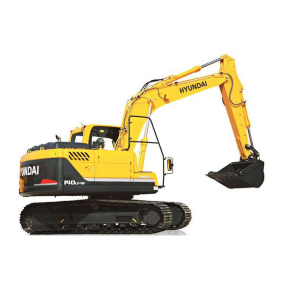
GROUP 2 SPECIFICATIONS GROUP 2 SPECIFICATIONS 1. MAJOR COMPONENT 1. MAJOR COMPONENT Tool box Fuel tank Hydraulic tank Main pump Engine Radiator Oil cooler Tooth Turning joint Swing motor Bucket Main control valve Arm cylinder Boom Boom cylinder Muffler Counterweight Bucket cylinder Sprocket Control link... -
Page 28: Specifications
2. SPECIFICATIONS R140LC-9S 4.60 m (15' 1") BOOM and 2.50 m (8' 2") ARM I(I') B(L) 1409S2SP02 Description Unit Specification Operating weight kg (lb) 13980 (30820) Bucket capacity (SAE heaped), standard 0.58 (0.76) Overall length 7810 (25' 7") Overall width, with 600 mm shoe 2600 (8' 6") Overall height of boom 2780 (9' 1") - Page 29 R140LC-9S, 4.90 m (16' 1") HYDRAULIC ADJUSTABLE BOOM and 2.50 m (8' 2") ARM 14092SP03 Description Unit Specification Operating weight kg (lb) 13980 (30860) Bucket capacity (SAE heaped), standard 0.58 (0.76) Overall length 8170 (26' 8") Overall width, with 600 mm shoe 2600 (8' 6") Overall height of boom 2940 (9' 8")
- Page 30 R140LCD-9S I(I') B(L) 1409S2SP04 Description Unit Specification Operating weight kg (lb) 14800 (32630) Bucket capacity (SAE heaped), standard 0.58 (0.76) Overall length 8210 (26' 11") Overall width, with 600 mm shoe 2600 (8' 6") Overall height of boom 2780 (9' 1") Superstructure width 2500 (8' 2") Overall height of cab...
- Page 31 R140LCM-9S I(I') B(L) 1409S2SP05 Description Unit Specification Operating weight kg (lb) 16880 (37210) Bucket capacity (SAE heaped), standard 0.58 (0.76) Overall length 7790 (25' 6") Overall width, with 800 mm shoe 2840 (9' 4") Overall height of boom 2830 (9' 3") Superstructure width 2500 (8' 2") Overall height of cab...
-
Page 32: Working Range
3. 3. WORKING RANGE WORKING RANGE R140LC/LCD-9S R140LC/LCD-9S 1) 1) (1) (1) 4.60 4.60 m (15' 1") MONO (15' 1") MONO BOOM BOOM 14092SP06 2.10 m (6' 11") Arm ※2.50 m ( 8' 2") Arm 3.00 m ( 9' 10") Arm Description 1.90 m (6' 3") Arm Max digging reach... - Page 33 (2) (2) 4.10 4.10 m (13' 5") MONO (13' 5") MONO BOOM BOOM 14092SP06 Description 1.90 m (6' 3") Arm 2.10 m (6' 11") Arm Max digging reach 7260 mm (23' 10") 7420 mm (24' 4") Max digging reach on ground 7090 mm (23' 3") 7260 mm (23'10") Max digging depth...
- Page 34 (3) (3) 4.90 4.90 m (16' 1") (16' 1") ADJUST BOOM ADJUST BOOM 14092SP08 Description 1.90 m (6' 3") Arm 2.10 m (6' 11") Arm 2.50 m ( 8' 2") Arm Max digging reach 8140 mm (26' 8") 8320 mm (27' 4") 8720 mm (28' 7") Max digging reach on ground 8000 mm (26' 3")
- Page 35 2) 2) R140LCM-9S R140LCM-9S 4.6 m (15' 1") (15' 1") MONO BOOM MONO BOOM (1) (1) 14092SP09 2.10 m (6' 11") Arm ※2.50 m ( 8' 2") Arm 3.00 m ( 9' 10") Arm Description 1.90 m (6' 3") Arm Max digging reach 7750 mm (25' 5") 7920 mm (26' 0")
-
Page 36: Weight
4. WEIGHT 4. WEIGHT 1) 1) R140LC-9S, R140LCD-9S R140LC-9S, R140LCD-9S R140LC-9S R140LCD-9S Item ← Upper structure assembly 5630 12420 ← Main frame weld assembly 1160 2560 ← Engine assembly ← Main pump assembly ← Main control valve assembly ← Swing motor assembly ←... - Page 37 2) 2) R140LCM-9S R140LCM-9S R140LCM-9S Item Upper structure assembly 5630 12420 Main frame weld assembly 1160 2560 Engine assembly Main pump assembly Main control valve assembly Swing motor assembly Hydraulic oil tank assembly Fuel tank assembly Counterweight 2000 4410 Cab assembly Lower chassis assembly 8700 19180...
-
Page 38: Lifting Capacities
5. LIFTING CAPACITIES 5. LIFTING CAPACITIES 1) 1) R140LC-9S R140LC-9S 4.60 m (15' 1") boom, 2.50 m (8' 2") arm equipped with 0.58 m (SAE heaped) bucket and 600 mm (24") triple grouser shoe and 2000 kg (4410 Ib) counterweight. ·... - Page 39 2) 2) R140LC-9S, R140LC-9S, ADJUST ADJUST BOOM BOOM 4.90 m (16' 1") adjust boom, 1.90 m (6' 3") arm equipped with 0.58 m (SAE heaped) bucket and 600 mm (24") triple grouser shoe and 2000 kg (4410 Ib) counterweight. · ·...
- Page 40 3) 3) R140LCD-9S R140LCD-9S 4.60 m (15' 1") boom, 1.9 m (6' 3") arm equipped with 0.58 m (SAE heaped) bucket and 600 mm (24") triple grouser shoe and 2000 kg (4410 Ib) counterweight. · · : Rating over-front : Rating over-side or 360 degree Load radius At max.
- Page 41 This as a preview PDF file from best-manuals.com Download full PDF manual at best-manuals.com...
Need help?
Do you have a question about the Robex 140LC-9S and is the answer not in the manual?
Questions and answers