Table of Contents
Advertisement
Quick Links
Advertisement
Table of Contents

Summary of Contents for Motorline professional MR30
- Page 1 MR30 MR30 USER'S AND INSTALLER'S MANUAL v2.1 REV. 09/2021...
-
Page 2: Table Of Contents
01. SAFETY INSTRUCTIONS This product is certified in accordance with European Community (EC) safety standards. 02. THE PRODUCT MR30 This product complies with Directive 2011/65/EU of the TECHNICAL CHARACTERISTICS European Parliament and of the Council, of 8 June 2011, on... -
Page 3: Safety Instructions
01. SAFETY INSTRUCTIONS GENERAL WARNINGS the risks and dangers involved. • Children shouldn’t play with the product or opening devices to avoid • This manual contains very important safety and usage information. the motorized door or gate from being triggered involuntarily. very important. - Page 4 01. SAFETY INSTRUCTIONS RESPONSABILITY health requirements for the use of work equipment workers at the work of Directive 2009/104/CE of European Parliament and of the • Supplier disclaims any liability if: Council of 16 September 2009. • Product failure or deformation result from improper installation •...
-
Page 5: The Product Mr30 4A
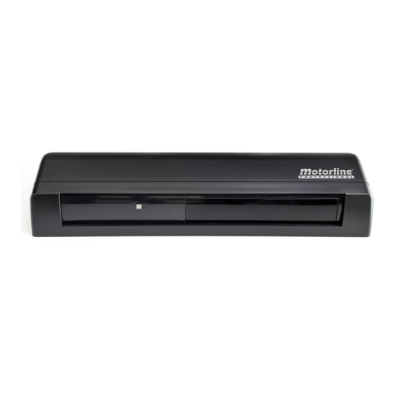
02. THE PRODUCT 02. THE PRODUCT MR30 DIMENSIONS The MR30 is an infrared radar with pedestrian safety and a detection area that is easily adjustable with precision to prevent false door openings. TECHNICAL CHARACTERISTICS • Power supply 12-24 Vac/dc 50/60Hz •... -
Page 6: Installation
03. INSTALLATION INSTALLATION AND CONNECTIONS To ensure that the MR30 works correctly, please observe the following instructions: • Prevent the installation area from accumulating snow or water on the ground; • Install in a protected area where rain or snow does not fall directly on the device. -
Page 7: Configuration
04. CONFIGURATION 04. CONFIGURATION DIP SWITCH SETTINGS PRESENCE TIMER 1 2 3 4 5 6 7 8 The sensor will detect a static object only for the time defined by the Presence Timer. Time Dip switch [3] Dip switch [4] Dip switch 1 2 3 4 5 6 7 8 ∞... -
Page 8: Safety Output 7A
04. CONFIGURATION 05. PROGRAMMING SAFETY OUTPUT TURN ON RADAR It is possible to define what type of contact the safety output will have. Before turning on the power, connect the door controller to the sensor. If there is a moving object in the detection area after initialization/reset, the sensor will be in motion detection Safety output Dip switch [6]... -
Page 9: Sensitivity Adjustment
05. PROGRAMMING 05. PROGRAMMING DETECTION AREA ADJUSTMENT SELF-MONITORING WIDTH ADJUSTMENT If self-monitoring determines that the sensor is not functioning properly, the relay output will cause the door to open and the green/red LED to flash. In that case, replace the sensor immediately. Adjust the detection width by turning the area tuner with a screwdriver. -
Page 10: Troubleshooting
06. TROUBLESHOOTING INSTRUCTIONS FOR FINAL CONSUMERS / SPECIALIZED TECHNICIANS Anomaly Cause Procedure • The connector is not connected correctly. • Tighten or reconnect the connector. The door does not work • Incorrect supply voltage. • Apply the appropriate voltage to the sensor (12-24Vac / dc). •...


Need help?
Do you have a question about the MR30 and is the answer not in the manual?
Questions and answers