Table of Contents
Advertisement
Quick Links
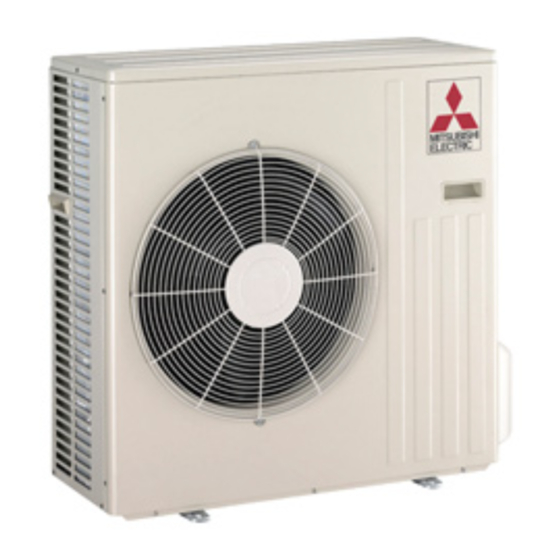
SPLIT-TYPE, HEAT PUMP AIR CONDITIONERS
OUTDOOR UNIT
SERVICE MANUAL
Wireless type
Model
MUH-GD80VB -
NOTE:
RoHS compliant products have <G> mark on the spec name plate.
HFC
utilized
R410A
E1
Indoor unit service manual
MSH-GD•VB Series (OBH513)
CONTENTS
1. TECHNICAL CHANGES ··································· 2
2. PART NAMES AND FUNCTIONS ····················· 2
3. SPECIFICATION ················································ 3
4. NOISE CRITERIA CURVES ······························ 3
5. OUTLINES AND DIMENSIONS ························ 4
6. WIRING DIAGRAM ············································ 4
7. REFRIGERANT SYSTEM DIAGRAM ··············· 5
8. PERFORMANCE CURVES ······························· 6
9. ACTUATOR CONTROL ··································· 10
10. SERVICE FUNCTIONS ·····································11
11. TROUBLESHOOTING ······································11
12. DISASSEMBLY INSTRUCTIONS ···················· 18
PARTS CATALOG (OBB514)
No. OBH514
Advertisement
Table of Contents

Subscribe to Our Youtube Channel
Related Manuals for Mitsubishi Electric MUH-GD80VB


Summary of Contents for Mitsubishi Electric MUH-GD80VB
-
Page 1: Table Of Contents
OUTDOOR UNIT No. OBH514 SERVICE MANUAL utilized R410A Wireless type Model MUH-GD80VB - Indoor unit service manual MSH-GD•VB Series (OBH513) CONTENTS 1. TECHNICAL CHANGES ··································· 2 2. PART NAMES AND FUNCTIONS ····················· 2 3. SPECIFICATION ················································ 3 4. NOISE CRITERIA CURVES ······························ 3 5. -
Page 2: Technical Changes
TECHNICAL CHANGES MUH-GD80VB - 1. New model PART NAMES AND FUNCTIONS MUH-GD80VB Air inlet (back and side) Air outlet ACCESSORIES MUH-GD80VB Drain socket Drain cap Drain cap —... -
Page 3: Specification
SPECIFICATION Outdoor model MUH-GD80VB Function Cooling Heating Single phase Power supply 230 V, 50 Hz Capacity Breaker capacity Running current (Total) 14.76 15.90 Power input (Total) 3,320 3,580 Power factor (Total) Starting current (Total) Coeffi cient of performance (C.O.P) (Total) 2.41... -
Page 4: Outlines And Dimensions
OUTLINES AND DIMENSIONS Unit: mm MUH-GD80VB Open as a rule 500 mm or more if REQUIRED SPACE the front and both sides are open 100 mm or more 200 mm or more if 100 mm or more there are obstacles... -
Page 5: Refrigerant System Diagram
REFRIGERANT SYSTEM DIAGRAM MUH-GD80VB Unit: mm Muffler Refrigerant pipe 15.88 #100 4-way valve (with heat insulator) Stop valve (with service port) Outdoor heat Flared connection Discharge exchanger temperature thermistor Defrost RT62 thermistor RT61 Muffler Compressor Ambient temperature thermistor RT63 Flared connection... -
Page 6: Performance Curves
PERFORMANCE CURVES MUH-GD80VB The standard specifications apply only to the operation of the air conditioner under normal conditions, since operating condi- tions vary according to the areas where these units are installed. The following information has been provided to clarify the operating characteristics of the air conditioner under the conditions indicated by the performance curve. - Page 7 Air flow should be set at MAX. The unit of pressure has been changed to MPa on the international system of units (SI unit system). The conversion factor is: 1(MPa [Gauge]) = 10.2 (kgf/ [Gauge]) MUH-GD80VB (kgf/ [Gauge])(MPa[Gauge]) MUH-GD80VB 230 V...
- Page 8 PERFORMANCE DATA COOL operation MSH-GD80VB: MUH-GD80VB (230V) CAPACITY : 8.0(kW) SHF : 0.62 INPUT : 3320(W) OUTDOOR DB(°C) INDOOR INDOOR DB(°C) WB(°C) SHF INPUT SHF INPUT SHF INPUT SHF INPUT 9.40 4.14 0.44 2656 9.00 3.96 0.44 2789 8.64 3.80 0.44...
- Page 9 PERFORMANCE DATA COOL operation MSH-GD80VB: MUH-GD80VB (230V) CAPACITY : 8.0(kW) SHF : 0.62 INPUT : 3320(W) OUTDOOR DB( °C ) INDOOR INDOOR DB(°C) WB(°C) SHF INPUT SHF INPUT SHF INPUT 7.84 3.45 0.44 3254 7.20 3.17 0.44 3453 6.92 3.04 0.44...
-
Page 10: Actuator Control
PERFORMANCE DATA HEAT operation MSH-GD80VB: MUH-GD80VB (230V) CAPACITY : 9.4(kW) INPUT : 3580(W) OUTDOOR WB(°C) INDOOR DB(°C) INPUT INPUT INPUT INPUT INPUT INPUT INPUT 5.92 2327 7.14 2792 8.37 3150 9.59 3401 10.81 3616 11.94 3723 13.16 3795 5.64 2506 6.77... -
Page 11: Service Functions
SERVICE FUNCTIONS MUH-GD80VB 10-1. COMPULSORY DEFROSTING MODE FOR SERVICE By short circuit of the connector JPG1 and R871 on the outdoor deicer P.C. board, defrosting mode can be accomplished regardless of the defrost interval restriction. (Refer to 11-4.) Defrost thermistor RT61 must read below -3°C. - Page 12 11-2. TROUBLE CRITERION OF MAIN PARTS MUH-GD80VB Part name Check method and criterion Figure Measure the resistance with a tester. (Part temperature –10°C ~ 40°C) Defrost thermistor (RT61) Refer to 11-4. "Test point diagram and voltage", "Outdoor deicer P.C. board", the chart of thermistor.
- Page 13 11-3. TROUBLESHOOTING FLOW Compressor and/or outdoor fan motor doesn’t operate. Check of outdoor unit Turn ON the power supply. Is there 230 V AC to Check the outdoor power supply between on the and connection of wiring. outdoor terminal block Compressor does not operate.
- Page 14 Compressor and/or outdoor fan motor doesn’t stop. Check of outdoor unit Turn OFF the power supply. After 30 seconds, turn ON the power supply again. Operate the unit in COOL or HEAT mode by pressing the EMERGENCY OPERATION switch. Operate the unit for 1 minute or more and stop it by pressing the EMERGENCY OPERATION switch again.
- Page 15 When OPERATION INDICATOR lamp flashes ON and OFF in every 0.5-second. Outdoor unit doesn’t operate. How to check mis-wiring Short circuit of JPG and JPS on the indoor electronic control P.C. board enables self -check to be displayed in 3 seconds. Start •...
- Page 16 When OPERATION INDICATOR lamp flashes 10-time. Heating/Cooling doesn't operate. Check of LEV (Expansion valve) Turn ON the power supply. During pressing both the OPERATION SELECT button and the TOO COOL button on the remote controller at the same time, press the RESET button. First, release the RESET button.
- Page 17 11-4. TEST POINT DIAGRAM AND VOLTAGE MUH-GD80VB Outdoor deicer P.C. board Defrost thermistor (RT61) Ambient temperature thermistor (RT63) Discharge temperature thermistor (RT62) -20 -10 10 20 30 40 0 10 20 30 40 50 60 70 80 90 100 110 120 Temperature (°C)
-
Page 18: Disassembly Instructions
Pull the terminal while pull out the terminal pushing the locking slowly. Locking lever lever. Connector MUH-GD80VB OPERATING PROCEDURE PHOTOS 1.Removing the cabinet Photo 1 Screw of the top panel (1) Remove the screws of the service panel. (2) Remove the screws of the top panel. - Page 19 OPERATING PROCEDURE PHOTOS 2. Removing the deicer P.C. board Photo 4 Deicer P.C. board Terminal (1) Remove the service panel and the cabinet. blocks (2) Disconnect all the connectors and the terminals on the deicer P.C. board. (3) Remove the deicer P.C. board. Screws of the relay...
- Page 20 HEAD OFFICE: TOKYO BLDG.,2-7-3, MARUNOUCHI, CHIYODA-KU, TOKYO 100-8310, JAPAN Copyright 2008 MITSUBISHI ELECTRIC ENGINEERING CO.,LTD New publication, effective Apr. 2008 Distributed in Apr. 2008. No.OBH514 6 Specifications subject to change without notice. Made in Japan...
- Page 21 Related Links Model Number: MUH-GD80VB MUH-GD80VB_Declaration_of_Conformity MUH-GD80_Parts_Catalog_(OBB514) MUH-GD80_Service_Manual_(OBH514)
Need help?
Do you have a question about the MUH-GD80VB and is the answer not in the manual?
Questions and answers