Table of Contents
Advertisement
SPLIT-TYPE, HEAT PUMP AIR CONDITIONERS
SERVICE MANUAL
Wireless type
Models
MSH-XV07UV -
MSH-XV09UV -
MSH-XV12UV -
·MUH-XV07UV -
( WH )
E1
·MUH-XV09UV -
( WH )
E1
·MUH-XV12UV -
( WH )
E1
CONTENTS
1. PART NAMES AND FUNCTIONS······················3
2. SPECIFICATION·················································5
3. NOISE CRITERIA CURVES ·······························7
4. OUTLINES AND DIMENSIONS ························ 8
5. WIRING DIAGRAM ··········································10
6. REFRIGERANT SYSTEM DIAGRAM ··············11
7. PERFORMANCE CURVES ······························13
8. MICROPROCESSOR CONTROL ····················29
9. SERVICE FUNCTIONS ····································38
10. TROUBLESHOOTING······································40
11. DISASSEMBLY INSTRUCTIONS·····················51
12. PARTS LIST······················································55
No. OB294
E1
E1
E1
Advertisement
Table of Contents

Subscribe to Our Youtube Channel
Related Manuals for Mitsubishi Electric MSH-XV07UV


Summary of Contents for Mitsubishi Electric MSH-XV07UV
-
Page 1: Table Of Contents
SPLIT-TYPE, HEAT PUMP AIR CONDITIONERS No. OB294 SERVICE MANUAL Wireless type Models MSH-XV07UV - ·MUH-XV07UV - ( WH ) MSH-XV09UV - ·MUH-XV09UV - ( WH ) MSH-XV12UV - ·MUH-XV12UV - ( WH ) CONTENTS 1. PART NAMES AND FUNCTIONS······················3 2. SPECIFICATION·················································5 3. -
Page 3: Part Names And Functions
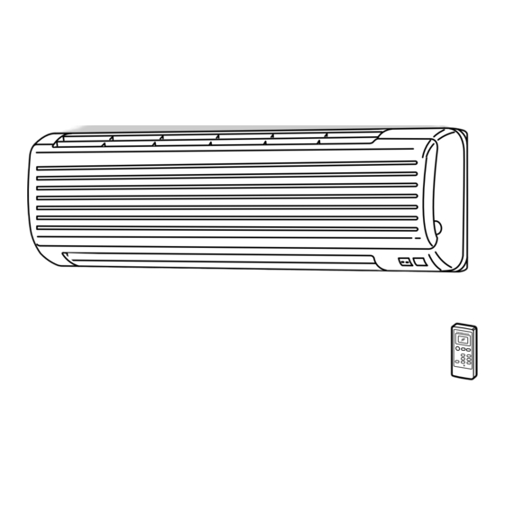
PART NAMES AND FUNCTIONS INDOOR UNIT MSH-XV07UV - MSH-XV12UV - MSH-XV09UV - Grille Deodorizing filter Air inlet (Gray sponge type) Air cleaning filter (White bellows type) Remote control receiving section Front panel Horizontal vane Air filter Remote controller Vertical vanes... -
Page 4: Msh-Xv12Uv - E1
ACCESSORIES MSH-XV07UV - MSH-XV12UV - MSH-XV09UV - <Indoor unit> Installation plate Installation plate fixing screw 4 x 25 mm Remote controller holder Fixing screw for 3 3.5 x 16 mm (Black) Battery (AAA) for remote controller Wireless remote controller Felt tape (Used for left or left-rear piping) -
Page 5: Specification
SPECIFICATION MSH-XV09UV - Indoor model MSH-XV07UV - Cooling Function Cooling Heating Heating Single phase Single phase Power supply 220-240V, 50Hz 220-240V, 50Hz Capacity Dehumidification — — 504/408W/306W 474/390W/306W Air flow(High/Med.W/LowW) K /h 534/438W/342W 474/390W/306W Power outlet 4.36-4.21 Running current 3.29-3.15 4.36-4.21... - Page 6 Indoor model MSH-XV12UV - Cooling Heating Function Single phase Power supply 220-240V, 50Hz 4.05 Capacity — Dehumidification Air flow(High/Med.W/LowW) 564/474W/384W 600/510W/432W K /h Power outlet 5.92-6.02 6.34-6.43 Running current 1,250-1,330 1,340-1,420 Power input Auxiliary heater A(kW) — 96-92 96-92 Power factor Starting current Fan motor current 0.19...
-
Page 7: Noise Criteria Curves
NOISE CRITERIA CURVES MSH-XV07UV - MSH-XV09UV - NOTCH SPL(dB(A)) LINE NOTCH SPL(dB(A)) LINE High High Test conditions, Test conditions, Cooling : Dry-bulb temperature 27: Wet-bulb temperature 19: Cooling : Dry-bulb temperature 27: Wet-bulb temperature 19: Heating : Dry-bulb temperature 20:... -
Page 8: Outlines And Dimensions
OUTLINES AND DIMENSIONS Unit: mm MSH-XV07UV - MSH-XV09UV - Installation plate INDOOR UNIT Indoor unit 81.5 116.5 Wall hole [65 Installation plate Liquid line [6.35-0.5m Gas line [9.52-0.43m Air in Insulation [37 O.D [21 I.D Drain hose [16 (Connected part O.D) 17.5... - Page 9 Unit: mm MUH-XV07UV - MUH-XV12UV - MUH-XV09UV - OUTDOOR UNIT REQUIRED SPACE Air in Air in Drainage 3holes [33 Airout Service panel Liquid refrigerant pipe joint Refrigerant pipe (flared) [6.35 Gas refrigerant pipe joint Refrigerant pipe (flared) [9.52 (MUH-XV07/09UV ) [12.7 (MUH-XV12UV )
-
Page 10: Wiring Diagram
WIRING DIAGRAM MSH-XV07UV - MSH-XV12UV - MODELS WIRING DIAGRAM MSH-XV09UV - INDOOR UNIT TO OUTDOOR UNIT CONNECTING RT12 RT11 CN201 NR11 220-240V~ SR141 LD103 CN211 POWER ELECTRONIC CONTROL P.C. BOARD SUPPLY CORD ~/N 220-240V 50Hz POWER MONITOR, RECEIVER P.C. BOARD... -
Page 11: Refrigerant System Diagram
REFRIGERANT SYSTEM DIAGRAM Unit:mm MSH-XV07UV - MUH-XV07UV - INDOOR UNIT Refrigerant pipe [ 9.52 4-way valve OUTDOOR UNIT (with heat insulator) Muffler Indoor coil Defrost Indoor Stop valve thermistor thermistor heat Outdoor (with service RT12 RT61 heat exchanger port) Flared connection... -
Page 12: High
MAX. REFRIGERANT PIPING LENGTH Refrigerant piping Piping size O.D : mm Length of connecting pipe : m Max. length : m Model Outdoor unit Liquid Indoor unit MSH-XV07UV - MUH-XV07UV - 9.52 Gas 0 MSH-XV09UV - Gas 0.43 6.35 Liquid 0.5 Liquid 0... -
Page 13: Performance Curves
PERFORMANCE CURVES MSH-XV07UV - MSH-XV12UV - MUH-XV07UV - MUH-XV12UV - MSH-XV09UV - MUH-XV09UV - The standard data contained in these specifications apply only to the operation of the air conditioner under normal conditions, since operating conditions vary according to the areas where these units are installed. The following information has been pro- vided to clarify the operating characteristics of the air conditioner under the conditions indicated by the performance curve. - Page 14 19.9 22.8 26.5 18.3 21.0 24.4 16.8 19.3 22.4 15.3 17.5 20.4 13.8 15.8 18.3 12.2 14.0 16.3 10.7 12.3 14.3 10.5 12.2 NOTE: The above curves are for the heating operation without any frost. OUTDOOR LOW PRESSURE AND OUTDOOR UNIT CURRENT COOL operation Air flow should be set at MAX.
- Page 15 MUH-XV12UV - MUH-XV12UV - (kgf/F[Gauge])(MPa[Gauge]) 240V 220V 220V-240V 30 32 35(:) 70(%) 70(%) Ambient temperature(˚C) Ambient humidity(%) Ambient temperature(˚C) Ambient humidity(%) HEAT operation Outdoor:Dry bulb temperature 7,15,20°C Condition indoor:Dry bulb temperature 20.0°C Wet bulb temperature 6,12,14.5°C Wet bulb temperature 14.5°C MUH-XV07UV - MUH-XV12UV - 240V...
- Page 16 PERFORMANCE DATA COOL operation MSH-XV07UV - : MUH-XV07UV - (220V) CAPACITY : 2.1(KW) SHF : 0.74 INPUT : 710(W) OUTDOOR DB(:) INDOOR INDOOR SHC SHF INPUT SHC SHF INPUT SHC SHF INPUT SHC SHF INPUT DB(:) WB(:) 2.47 1.38 0.56 2.36...
- Page 17 PERFORMANCE DATA COOL operation MSH-XV07UV - : MUH-XV07UV - (220V) CAPACITY : 2.1(KW) SHF : 0.74 INPUT : 710(W) OUTDOOR DB(:) INDOOR INDOOR SHC SHF INPUT SHC SHF INPUT SHC SHF INPUT SHC SHF INPUT DB(:) WB(:) 2.06 1.15 0.56 1.89...
-
Page 18: Muh-Xv07Uv - E1
PERFORMANCE DATA COOL operation MSH-XV07UV - : MUH-XV07UV - (240V) CAPACITY : 2.1(KW) SHF : 0.74 INPUT : 740(W) OUTDOOR DB(:) INDOOR INDOOR SHC SHF INPUT SHC SHF INPUT SHC SHF INPUT SHC SHF INPUT DB(:) WB(:) 2.47 1.38 0.56 2.36... -
Page 19: Muh-Xv07Uv - E1
PERFORMANCE DATA COOL operation MSH-XV07UV - : MUH-XV07UV - (240V) CAPACITY : 2.1(KW) SHF : 0.74 INPUT : 740(W) OUTDOOR DB(:) INDOOR INDOOR SHC SHF INPUT SHC SHF INPUT SHC SHF INPUT SHC SHF INPUT DB(:) WB(:) 2.06 1.15 0.56 1.89... -
Page 20: Muh-Xv09Uv - E1
PERFORMANCE DATA COOL operation MSH-XV09UV - : MUH-XV09UV - (220V) CAPACITY : 2.5(KW) SHF : 0.7 INPUT : 940(W) OUTDOOR DB(:) INDOOR INDOOR SHC SHF INPUT SHC SHF INPUT SHC SHF INPUT SHC SHF INPUT DB(:) WB(:) 2.94 1.53 0.52 2.81 1.46 0.52... -
Page 21: Muh-Xv09Uv - E1
PERFORMANCE DATA COOL operation MSH-XV09UV - : MUH-XV09UV - (220V) CAPACITY : 2.5(KW) SHF : 0.7 INPUT : 940(W) OUTDOOR DB(:) INDOOR INDOOR SHC SHF INPUT SHC SHF INPUT SHC SHF INPUT SHC SHF INPUT DB(:) WB(:) 2.45 1.27 0.52 2.25 1.17 0.52... -
Page 22: Muh-Xv09Uv - E1
PERFORMANCE DATA COOL operation MSH-XV09UV - : MUH-XV09UV - (240V) CAPACITY : 2.5(KW) SHF : 0.7 INPUT : 970(W) OUTDOOR DB(:) INDOOR INDOOR SHC SHF INPUT SHC SHF INPUT SHC SHF INPUT SHC SHF INPUT DB(:) WB(:) 2.94 1.53 0.52 2.81 1.46 0.52... -
Page 23: Muh-Xv09Uv - E1
PERFORMANCE DATA COOL operation MSH-XV09UV - : MUH-XV09UV - (240V) CAPACITY : 2.5(KW) SHF : 0.7 INPUT : 970(W) OUTDOOR DB(:) INDOOR INDOOR SHC SHF INPUT SHC SHF INPUT SHC SHF INPUT SHC SHF INPUT DB(:) WB(:) 2.45 1.27 0.52 2.25 1.17 0.52... - Page 24 PERFORMANCE DATA COOL operation MSH-XV12UV - : MUH-XV12UV - (220V) CAPACITY : 3.4(KW) SHF : 0.67 INPUT : 1250(W) OUTDOOR DB(:) INDOOR INDOOR SHC SHF INPUT SHC SHF INPUT SHC SHF INPUT SHC SHF INPUT DB(:) WB(:) 4.00 1.96 0.49 1000 3.83 1.87...
- Page 25 PERFORMANCE DATA COOL operation MSH-XV12UV - : MUH-XV12UV - (220V) CAPACITY : 3.4(KW) SHF : 0.67 INPUT : 1250(W) OUTDOOR DB(:) INDOOR INDOOR SHC SHF INPUT SHC SHF INPUT SHC SHF INPUT SHC SHF INPUT DB(:) WB(:) 3.33 1.63 0.49 1225 3.06 1.50...
- Page 26 PERFORMANCE DATA COOL operation MSH-XV12UV - : MUH-XV12UV - (240V) CAPACITY : 3.4(KW) SHF : 0.67 INPUT : 1330(W) OUTDOOR DB(:) INDOOR INDOOR SHC SHF INPUT SHC SHF INPUT SHC SHF INPUT SHC SHF INPUT DB(:) WB(:) 4.00 1.96 0.49 1064 3.83 1.87...
- Page 27 PERFORMANCE DATA COOL operation MSH-XV12UV - : MUH-XV12UV - (240V) CAPACITY : 3.4(KW) SHF : 0.67 INPUT : 1330(W) OUTDOOR DB(:) INDOOR INDOOR SHC SHF INPUT SHC SHF INPUT SHC SHF INPUT SHC SHF INPUT DB(:) WB(:) 3.33 1.63 0.49 1303 3.06 1.50...
-
Page 28: Muh-Xv07Uv - E1
PERFORMANCE DATA HEAT operation MSH-XV07UV - : MUH-XV07UV - (220V) CAPACITY : 2.4(KW) INPUT : 670(W) OUTDOOR WB(:) INDOOR DB(:) INPUT INPUT INPUT INPUT INPUT INPUT INPUT 1.51 1.82 2.14 2.45 2.76 3.05 3.36 1.44 1.73 2.04 2.33 2.64 2.93 3.23... -
Page 29: Microprocessor Control
MICROPROCESSOR CONTROL MSH-XV07UV - MSH-XV12UV - MUH-XV07UV - MUH-XV12UV - MSH-XV09UV - MUH-XV09UV - WIRELESS REMOTE CONTROLLER Once the operation mode are set, the same operation mode can be repeated by simply turning the OPERATE/STOP button ON. Indoor unit receives the signal with a beep tone. -
Page 30: Continuous
(4) The initial set temperature is decided by the initial room temperature. Initial set temperature Mode Initial room temperature 26: or more COOL mode of "I FEEL CONTROL" Initial room temperature 25: to 26: minus 2: DRY mode of Initial room temperature 23: to 25: "I FEEL CONTROL"... -
Page 31: Continuous
Time control When the three conditions as follows have been satisfied for 1 hour and 45 minutes, the compressor stops for 3 minutes. The indoor fan operates at the set speed. a. Compressor has been continuously operating. b. Indoor fan speed is Low or Med.. c. - Page 32 (2) Cold air prevention control 1 When the compressor is not operating, (1) if the temperature of indoor coil thermistor RT12 is 18°C or less, the fan stops. (2) if the temperature of indoor coil thermistor RT12 is more than 18°C, the fan operates at Very Low. 2 When the compressor is operating, (1) if the temperature of RT12 is 22°C or more, the fan operates at set speed.
- Page 33 3. Defrosting Defrosting of outdoor heat exchanger is controlled by DEICER P.C. board, with detection by the defrost thermistor RT61. (1) Starting conditions of defrost When all conditions of a) ~ c) are satisfied, the defrosting operation starts. a) The compressor cumulative operation time exceeds 40 minutes without the defrosting operation working. b) RT61 reads - 3.0°C or less.
- Page 34 4. R.V. coil control Heating · · · · · ON Cooling · · · · · OFF Dry · · · · · · · · OFF NOTE : The 4-way valve reverses for 5 seconds right before start-up of the compressor. Operation time chart (HEAT) (COOL / DRY)
- Page 35 8-5. FAN MOTOR CONTROL (1) Rotational frequency feedback control The indoor fan motor is equipped with a rotational frequency sensor, and outputs signal to the microprocessor to feedback the rotational frequency. Comparing the current rotational frequency with the target rotational frequency (High, Med., Low), the microprocessor controls SR141 and adjusts fan motor electric current to make the current rotational frequency close to the target rotational frequency.
- Page 36 (5) Dew prevention During COOL or DRY operation at Vane Angle 4 or 5 when the cumulative operation time of compressor exceeds 1 hour, the vane angle automatically changes to Angle 1 for dew prevention. (6) SWING MODE ( By selecting SWING mode with the VANE CONTROL button, the horizontal vane swings vertically. The remote controller displays “...
-
Page 37: Continuous
8-7. TIMER OPERATION 1. How to set the timer (1) Press the OPERATE/STOP (ON/OFF) button to start the air conditioner. SELECT (2) Press the TIMER MODE SELECT button to select the operation. (OFF TIMER) (ON TIMER) “ ” “ ” TIMER RELEASE Each time this button is pressed, the timer mode is changed in sequence. -
Page 38: Service Functions
SERVICE FUNCTIONS MSH-XV07UV - MSH-XV12UV - MUH-XV07UV - MUH-XV12UV - MSH-XV09UV - MUH-XV09UV - 9-1. COMPULSORY DEFROSTING MODE FOR SERVICE By short circuit of the connector JPDS and JPSG on the outdoor deicer P.C. board, defrosting mode can be accom- plished regardless of the defrost interval restriction. - Page 39 How to set the remote controller exclusively for particular indoor unit After you turn the breaker ON, the first remote controller that sends the signal to the indoor unit will be regarded as the remote controller for the indoor unit. The indoor unit will only accepts the signal from the remote controller that has been assigned to the indoor unit once they are set.
-
Page 40: Troubleshooting
TROUBLESHOOTING MSH-XV07UV - MSH-XV12UV - MUH-XV07UV - MUH-XV12UV - MSH-XV09UV - MUH-XV09UV - 10-1. Cautions on troubleshooting 1. Before troubleshooting, check the following: 1) Check the power supply voltage. 2) Check the indoor/outdoor connecting wire for mis-wiring. 2. Take care the following during servicing. - Page 41 10-2. Instruction of troubleshooting 1<The case of the trouble of the serial signal> When the power is turned off and then turned on again, the indication shows “the trouble of mis- Start wiring.” Indoor unit Indoor unit Indoor unit OPERATION INDICATOR operates.
- Page 42 1. Troubleshooting check table •The following indication applies regardless of shape of the indicator. flashing · Flashing of the OPERATION INDICATOR lamp (on the left-hand side) Operation Indicator indicates possible abnormalities. · The OPERATION INDICATOR lamp (on the left-hand side) is lighting during normal operation.
-
Page 43: Muh-Xv07Uv - E1
2. Trouble criterion of main parts MSH-XV07UV - MSH-XV12UV - MUH-XV07UV - MUH-XV12UV - MSH-XV09UV - MUH-XV09UV - Part name Check method and criterion Figure Room Measure the resistance with a tester. (Part temperature 10°C ~ 30°C) temperature thermistor(RT11) Normal... -
Page 44: Noise
When OPERATION INDICATOR lamp flashes 3-time. Indoor fan motor doesn’t operate. Check of indoor fan motor Turn OFF the power supply. Check connector CN211 visually. Is soldered point of the connector Are lead wires connected? correctly soldered? Re-connect the lead wires. Re-solder it. - Page 45 The unit doesn’t operate with the remote controller. Also, the OPERATION INDICATOR lamp doesn’t light up by pressing the EMERGENCY OPERATION switch. Check of indoor electronic control P.C. board Check the both “parts side” and “pattern side” of indoor electronic control P.C. board visually.
- Page 46 Compressor and / or outdoor fan motor doesn’t operate. Check of outdoor unit Start Operate the unit in COOL or HEAT mode by pressing the EMERGENCY OPERATION switch. 3-minute time delay works. Test run operation operates for 30 minutes. Compressor Rectify the indoor/outdoor doesn't operate.
- Page 47 When OPERATION INDICATOR lamp flashes ON and OFF in every 0.5-second or flashes once. Outdoor unit doesn’t operate. How to check mis-wiring and serial signal error Start 1 Short circuit of JPG and JPS on the 1. Turn OFF the power supply. indoor electronic control P.C.
- Page 48 When OPERATION INDICATOR lamp flashes 6-time. Thermistors in the outdoor unit are abnormal. Check of outdoor thermistor W Disconnect the connector CN661 from the deicer P.C. board. (Check the characteristics of thermistor.) Replace the deicer P.C. board. Defrost thermistor (RT61) Re-connect CN661.
- Page 49 TEST POINT DIAGRAM AND VOLTAGE MSH-XV07UV - MSH-XV12UV - MSH-XV09UV - Indoor electronic control P.C. board Power supply input Fuse 250V AC 3.15A Varistor (NR11) 220-240V Fan motor power supply CN111 Room temperature thermistor(RT11) CN112 Indoor coil CN201 thermistor(RT12) 12V DC –...
- Page 50 MUH-XV07UV - MUH-XV12UV - MUH-XV09UV - Outdoor deicer P.C. board Power supply input CN711 CN721 220-240V AC Outdoor fan motor R.V. coil 220-240V AC 220-240V AC NR61 Varistor Fuse 2A/250V R601 5~10VDC Defrost interval time short pin (JPDS, JPSG) (Refer to page 38.) Jumper wire for change in defrost setting...
-
Page 51: Disassembly Instructions
1Hold the sleeve, and 2Pull the terminal while pull out the terminal pushing the locking slowly. Locking lever lever. Connector 11-1. MSH-XV07UV - MSH-XV09UV - MSH-XV12UV - INDOOR UNIT OPERATING PROCEDURE PHOTOS 1. Removing the front panel Photo 1 (1) Remove the screw caps of the front panel. - Page 52 OPERATING PROCEDURE PHOTOS 3. Removing the electrical box Photo 3 Screw of the ground wire (1) Remove the front panel. (Refer to 1) (2) Remove the electrical cover. (Refer to 2) (3) Disconnect the connector of the indoor coil thermistor. (4) Disconnect the motor connector (CN211 and CN121) and the vane motor connector (CN151) on the electronic control P.C.
- Page 53 11-2. MUH-XV07UV - MUH-XV09UV - MUH-XV12UV - OUTDOOR UNIT NOTE: These photos use MUH-XV12UV - MUH-XV07UV - or MUH-XV09UV - is almost the same as MUH-XV12UV - OPERATING PROCEDURE PHOTOS 1. Removing the cabinet Photo 1 Screws of the front panel (1) Remove the screws of the top panel.
- Page 54 OPERATING PROCEDURE PHOTOS 3. Removing the propeller fan and the outdoor fan motor Photo 5 (1) Remove the cabinet. (Refer to 1.) (2) Remove the propeller fan nut. Set screws of the (3) Remove the propeller fan. outdoor fan motor Outdoor NOTE : Loose the propeller fan in the rotating direction for fan motor...
-
Page 55: Parts List
PARTS LIST MSH-XV07UV - (WH) MSH-XV09UV - (WH) MSH-XV12UV - (WH) 12-2. REMOTE CONTROLLER AND 12-1. INDOOR UNIT STRUCTURAL PARTS REMOTE CONTROLLER HOLDER (See page 59.) (See page 59.) (See page 59.) 12-1. INDOOR UNIT STRUCTURAL PARTS Q'ty/unit Symbol MSH-XV07... - Page 56 MSH-XV07UV - (WH) MSH-XV09UV - (WH) MSH-XV12UV - (WH) 12-3. INDOOR UNIT ELECTRICAL PARTS 12-4. INDOOR UNIT HEAT EXCHANGER AND FUNCTIONAL PARTS SLEEVE BEARING ROOM TEMPERATURE THERMISTOR FUSE VARISTOR 12-3. INDOOR UNIT ELECTRICAL PARTS AND FUNCTIONAL PARTS Part number that is circled is not shown in the illustration.
- Page 57 MUH-XV07UV - MUH-XV09UV - MUH-XV12UV - 12-5. OUTDOOR UNIT STRUCTURAL PARTS These figures show about MUH-XV12UV. Part numbers that are circled are not shown in the illustration. Q'ty/unit Symbol in Wiring Remarks Part name MUH-XV12 Part No. MUH-XV09 MUH-XV07 Diagram E02 336 297 TOP PANEL E02 679 630...
- Page 58 MUH-XV07UV - MUH-XV09UV - MUH-XV12UV - 12-6. OUTDOOR UNIT 12-7. ACCESSORY ELECTRICAL PARTS AND FUNCTIONAL PARTS 12-6. OUTDOOR UNIT ELECTRICAL PARTS AND FUNCTIONAL PARTS Part numbers that are circled are not shown in the illustration. Q'ty/unit Symbol MUH-XV12 Part No. in Wiring MUH-XV07 MUH-XV09...
-
Page 59: Deodorizing Filter
Clogged AIR CLEANING FILTER may reduce the air conditioner capacity or cause frost on the air outlet. DO NOT reuse AIR CLEANING FILTER even if it is washed. DO NOT remove or attach AIR CLEANING FILTER during unit operation. Model Part No. MSH-XV07UV- MSH-XV09UV- MAC-1300FT MSH-XV12UV- 12-9. DEODORIZING FILTER DEODORIZING FILTER removes ammonia and hydrogen sulphide emitted from tobacco, and odor of pets. - Page 60 HEAD OFFICE: MITSUBISHI DENKI BLDG.,2-2-3, MARUNOUCHI, CHIYODA-KU, TOKYO100-8310, JAPAN C C Copyright 2002 MITSUBISHI ELECTRIC ENGINEERING CO.,LTD New publication, effective Jan. 2002 Distributed in Jan. 2002. No.OB294 222 Specifications subject to change without notice. Made in Japan...
Need help?
Do you have a question about the MSH-XV07UV and is the answer not in the manual?
Questions and answers