Table of Contents
Advertisement
Vacuum pumps that pump nitrogen gas at pumping
speed of 15000L/S or more fall under row 2(35) of
appended table 1 of Japan's Export Trade Control Order,
which is based on international export control regimes.
Customers must follow all related rules and regulations
such as Foreign Exchange and Foreign Trade Act and
take
re-exporting those products.
D/N.MD30XVRE, 2018MH19
C30V
Maintenance, and Troubleshooting
Export Control Policy
appropriate
procedures
ULVAC CRYOGENICS INCORPORATED
R series Compressor Unit
_
for Cryopump and Super Trap
Installation, Operation,
C30V
R, C30V
_
C30MV
C30MVE
when
exporting
Instructions
RT, C30PV
RT
_
_
R, C30MV
RT
_
_
R, C30MVE
RT
_
_
or
Advertisement
Table of Contents
Troubleshooting

Related Manuals for Ulvac C30VR Series

Summary of Contents for Ulvac C30VR Series
- Page 1 Customers must follow all related rules and regulations such as Foreign Exchange and Foreign Trade Act and take appropriate procedures when exporting re-exporting those products. ULVAC CRYOGENICS INCORPORATED D/N.MD30XVRE, 2018MH19...
- Page 3 As a general rule, diagnosis of failure should be done on site by customer. However, ULVAC CRYOGENICS or our service network can perform this service for an agreed fee upon the customer’s request. There will be no charge if the cause...
- Page 4 ULVAC CRYOGENICS. (2) Damage during transportation When damage by delivery/transportation is admitted, the product will be repaired free of charge within the range of the guarantee expressed in the sales contract.
- Page 5 2.3 Repair period after production is discontinued ULVAC CRYOGENICS shall accept product repairs for seven years after production of the product is discontinued. 3. Service Form After the products are delivered, please fill out the following information in the blanks. If you have any questions or technical problems please feel free to contact the nearest Customer Support Center or headquarters.
- Page 6 (3) If you have any questions or comments on this document, please do not hesitate to contact us. The phone numbers of local customer support centers are listed at the end of this manual. ULVAC CRYOGENICS INCORPORATED...
- Page 7 There is a danger of fire or burn injury. Explosive gas used. There is a risk of fire or explosion. Hazardous voltage . Electric shock may cause severe injury or loss of life. Hot heating part present. There is a risk of burn injury. MZ0F001E,2013OR03 ULVAC CRYOGENICS INCORPORATED...
- Page 8 This page intentionally left blank ULVAC CRYOGENICS INCORPORATED...
-
Page 9: Table Of Contents
Verification of helium static pressure ······················································ 5-1 Compressor operation ········································································ 5-2 Inspection after replacing helium circulation components ··························· 5-4 Precautions for when compressor is not in operation ································· 5-5 Maintenance operation for a compressor suspended for a long period ·········· 5-5 ULVAC CRYOGENICS INCORPORATED... - Page 10 Figure 2-9 Signal delay when powered on(In Alternate operating mode) ············ 2-13 Figure 2-10 Signal delay when the time period from a stop to a restart is short ······· 2-14 Figure 2-11 Timing chart of C30VR when a short power interruption occurs ·········· 2-14 ULVAC CRYOGENICS INCORPORATED...
- Page 11 Figure C-2 C30MVR and C30MVER schematic diagram ·································· C-3 Figure C-3 C30V RT and C30PV RT schematic diagram ··································· C-4 Figure C-4 C30MV RT and C30MVE RT schematic diagram ······························ C-5 Figure D-1 Compressor flow diagram ··························································· D-2 ULVAC CRYOGENICS INCORPORATED...
- Page 12 Table 8-2 List of troubleshooting during operation ··········································· 8-3 Table A-1 Operating log ············································································· A-1 Table B-1 Combination of C30VR series compressor and cryopump/supertrap ······ B-1 Table C-1 Differences on devices between compressor unit models ··················· C-1 ULVAC CRYOGENICS INCORPORATED...
-
Page 13: Compressor Unit Safety Instructions
/ stopped into 6 times or less per hour also. Do not turn on and off the compressor to control the temperature of super trap. Please contact us when controlling the temperature of super trap is required. ULVAC CRYOGENICS INCORPORATED... - Page 14 ☆We collect used adsorbers. If there is any used absorber, please contact a person in your local dealership or Ulvac Techno Ltd. to have it picked up or send it directory to our Service Engineering Division. We only accept CTI adsorbers and our adsorbers.
-
Page 15: Table 1-6 Electromagnetic Environment Resistance Characteristics
Also, parts of inside the compressor unit are still hot just after the compressor has been stopped. Wait at least 15 minutes to open the cover to avoid the risk of burns. ULVAC CRYOGENICS INCORPORATED... - Page 16 This page intentionally left blank. ULVAC CRYOGENICS INCORPORATED...
-
Page 17: Disposal Considerations
We will offer you Material Safety Data Sheet (called MSDS) of our products upon your request. If you have any questions, please contact our Service Engineering Division or the nearest customer support center. MDIW001E,2010.06 ULVAC CRYOGENICS INCORPORATED IW-1... - Page 18 This page intentionally left blank. IW-2 ULVAC CRYOGENICS INCORPORATED...
-
Page 19: C30Vr_Compressor Description
M = Multiple (Max. 3 refrigerators) T = 3 phase motor drive Power consumption Blank= Standard E = Power saving 1:Standard helium gas filling pressure is different between a pump and a trap. Figure 1-1 C30VR Compressor models ULVAC CRYOGENICS INCORPORATED... -
Page 20: Terminology
Roles of compressor in cryopump system The cryopump system is consists of a cryopump and a compressor and is capable of condensing and adsorbing almost all kinds of gas molecule inside the pump. Thus clean ULVAC CRYOGENICS INCORPORATED... -
Page 21: Compressor Specifications
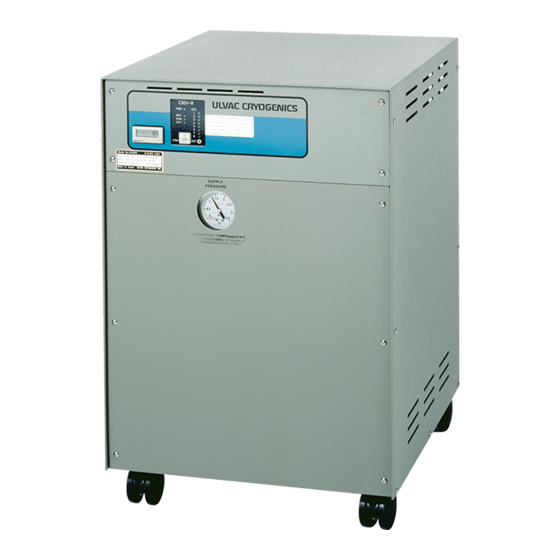
The Compressor requires maintenance. Read “Section 7 Maintenance” thoroughly and conduct regular maintenance. Compressor specifications Compressor specifications 1.6.1 External view 1.6.1 External view Figure 1-2 shows external view of C30VR. Figure 1-2 shows external view of C30VR. (Front) (Front) (Rear) (Rear) Figure 1-2 C30VR External view ULVAC CRYOGENICS INCORPORATED... -
Page 22: Figure 1-3 C30Vr Front Panel (Part)
Figure 1-4 C30MVR Front panel (Part) CAUTION Do not plac objects or equipments on top of a compressor. It prevents heat to be released from compressors as well as applying unnecessary heat to the equipments placed on it. ULVAC CRYOGENICS INCORPORATED... -
Page 23: Table 1-2 Compressor Weight
*The weights in this table are of standard compressors. The weight depends on the specifications of the customer’s order. 1.6.4 General specifications The tables below show power supply rating, cooling water requirements, installation environment, operation requirements and electromagnetic environment resistance characteristics. (Tables 1-3 ~1-6) ULVAC CRYOGENICS INCORPORATED... -
Page 24: Table 1-4 Cooling Water Requirements
Free from metal powder, dust, flammable and corrosive gas Static helium pressure 1.3±0.04MPaG 1.2±0.04MPaG 1.4±0.04MPaG at 20 ℃ (*1) Sound pressure level < 70 dBA during operation (*1) Refer to “Section5.1 Verification of helium static pressure” for details. ULVAC CRYOGENICS INCORPORATED... -
Page 25: Component Descriptions
Compressor front view is shown in Figure 1-6 and rear view in Figure 1-7 (both C30MVR). ①ELAPSED TIME METER FRONT PANEL ②HIGH PRESSURE HELIUM GAS PRESSURE GAUGE ③COM :MONITORING PORT ⑥ALARM STATUS TABLE ④HELIUM FILL FITTING ⑦ STATUS DISPLAY and (inside the panel) RESET BUTTON ⑤CASTERS Figure 1-6 Compressor front view ULVAC CRYOGENICS INCORPORATED... - Page 26 Refer to “Section 5.1 Verification of helium static pressure” to verify the helium pressure when the compressor is not in operation. ULVAC CRYOGENICS INCORPORATED...
- Page 27 Please contact us if fixing brackets need to be attached to the compressor. Figure -8 shows an example of anchor bolts mounting positions when fixing brackets are attach to the compressor. 8-M10 anchor volt Front Figure 1-8 Anchor bolts mounting positions (example) ULVAC CRYOGENICS INCORPORATED...
- Page 28 The Compressor unit is supplied main power from the distribution panel of the customers’ system. The distribution panel must have an appropriate circuit breaker for the compressor in accordance with the national and local codes and standards of the applicabl country. 1-10 ULVAC CRYOGENICS INCORPORATED...
- Page 29 The cryopump and the compressor can be operated through the remote cables. It also enables sending of operation answer-back signals and alarm signals activated in an event of compressor failure to the equipment-side. Refer to “Section 2.6 Remote functions” for details of remote functions. ULVAC CRYOGENICS INCORPORATED 1-11...
-
Page 30: Cryo-U Cryopump Multiple Installation
For detailed instructions on cryopump installation with compressor, refer to “Section 4.4 Single cryopump installation” and “Section 4.5 Multiple cryopump installation” Helium supply lines Helium return lines Remote cable Helium Refrigerator cables manifolds Cooling water AC Input power Figure 1-9 Cryopump installation with C30MVR compressor 1-12 ULVAC CRYOGENICS INCORPORATED... -
Page 31: Compressor With Inverter For Refrigerator
Wire connections and the settings such as inverter frequency depend on your application and system. Please consult with our Service Engineering Division or contact to the nearest customer support center. Rear Front Figure 1-10 C30VR compressor with inverter ULVAC CRYOGENICS INCORPORATED 1-13... - Page 32 C30VR Compressor Instruction Manual This page intentionally left blank. 1-14 ULVAC CRYOGENICS INCORPORATED...
-
Page 33: Considerations Before Installation
In addition, easy access the handle of main circuit protector (MCP) on the back must be ensured. Refer to Figure 1-5 in Section 1 for the dimensions of the compressor. ULVAC CRYOGENICS INCORPORATED... -
Page 34: Wiring Requirements
Refer to Table 1-3 in section 1 for circuit breaker current rating. CAUTION In most standards, it is required to install a branch breaker to protect power cables connected to the equipments. A circuit breaker must be installed. Failure to follow this procedure could seriously damage the equipment. ULVAC CRYOGENICS INCORPORATED... -
Page 35: Figure 2-2 Equipment-Side Power Circuit
It is a specialized cable compatible with conventional general-purpose compressors such as C30V and C30MV. Current rating of the refrigerator is less than 0.7A. ATTENTION: Refer to “Section 4 Equipment Installation, Piping, and Wiring” for routing of the cables above. ULVAC CRYOGENICS INCORPORATED... -
Page 36: Cooling Water Requirements
0.04MPa at a flow rate of 7L/min. Determine the values for water flow late and pressure loss so that the compressor can be run with an enough margin to the water temperature change throughout the year. ULVAC CRYOGENICS INCORPORATED... - Page 37 Operating water upper temperature range limit Allowable temperature (See CAUTION above) Temperature lower limit (2) > 7 L/min Water flow rate [L/min.] Figure 2-3 Cooling water flow rate, water supply temperature, and water pressure loss (Except for C30PVRT) ULVAC CRYOGENICS INCORPORATED...
- Page 38 It is recommended to install a filter in the “Cooling water inlet” line in order to remove contaminant in the cooling water. Installing a water flow meter in the cooling water line of the compressor is also recommended. ULVAC CRYOGENICS INCORPORATED...
-
Page 39: Length Of Cables And Flexible Hoses
Signal Quantity Photo Coupler Isolation Input C30VR Maximum Input voltage: 26VDC, Input Current: less than Input C30MVR Rated Input Voltage: ON:20V and above, OFF:3V or less C30VR No-voltage a contact Output Maximum Load: 30VDC / 100mA C30MV_R ULVAC CRYOGENICS INCORPORATED... -
Page 40: Figure 2-5 Remote Input Interface Circuit
Since it is the contact output, the polarity of DC24V in Figure 2-6 can be reversed. Make provisions for the interface circuit at the equipment side. (Equipment side) SIG1 SIG2 Relay Figure 2-6 Remote output interface circuit ULVAC CRYOGENICS INCORPORATED... - Page 41 The operating mode is switched automatically.The operating mode is determined by recognizing into which input pin the operation command of the compressor has entered after turning on the power supply. Once the operating mode is selected, the mode will be kept until the compressor is turned off. ULVAC CRYOGENICS INCORPORATED...
- Page 42 When the compressor pump is not in operation, it will not return the answer back signal (CH* ACK) even if this signal (CH* REF) is turned ON. Note: For the operation after a short power interruption, refer to “Section 2.6.6 Signal timing charts – Operation after a short power interruption”. 2-10 ULVAC CRYOGENICS INCORPORATED...
- Page 43 CH1 ACK, CH2 ACK, CH3 ACK(Refrigerators No.1-3 answer-back) These signals are required for C30MVR only. They are Answer-back output signals responding to each refrigerator command (CH* REF). When the refrigerators start operation, these answer-back signals will be sent to the equipment. ULVAC CRYOGENICS INCORPORATED 2-11...
-
Page 44: Figure 2-7 Timing Chart For Alternate Operating Mode With Two Refrigerators
0.3 seconds delay in response to a command signal. In the following conditions, however, the answer-back signal is sent behind time: (a) When the power supply of the compressor is turned ON 2-12 ULVAC CRYOGENICS INCORPORATED... -
Page 45: Figure 2-9 Signal Delay When Powered On(In Alternate Operating Mode
Note: Figure 2-11 leads the following equation: td + tw + 1 <= 2+ 5 + 1 = 8 (seconds) Where, “1” second is a margin added. ULVAC CRYOGENICS INCORPORATED 2-13... -
Page 46: Figure 2-10 Signal Delay When The Time Period From A Stop To A Restart Is Short
(*1) t≦ 2seconds td(*1) tw≧5seconds INPUT POWER SUPPLY COMP START COMP STOP CH1 REF COMP RUN CH1 ACK COMP OPERATION CH1 OPERATION Figure 2-11 Timing chart of C30VR when a short power interruption occurs (In Momentary operating mode) 2-14 ULVAC CRYOGENICS INCORPORATED... - Page 47 In “Alternate operating mode”, the compressor restarts as soon as the input power is recovered because there is always the command from the equipment side. NOTE: Refer to “Section 4.6.2 Connecting remote cables” for remote signal wiring. ULVAC CRYOGENICS INCORPORATED 2-15...
- Page 48 C30VR Compressor Installation, Operation, Maintenance and Troubleshooting This page intentionally left blank. 2-16 ULVAC CRYOGENICS INCORPORATED...
-
Page 49: Unpacking And Inspection
Inspect the carton before unpacking for evidence of damage such as dents, breakage, wetness and/or signs that the carton has been tipped over. If there is any damage please contact the delivery company immediately. Figure 3-1 Appearance of compressor carton ULVAC CRYOGENICS INCORPORATED... -
Page 50: Unpacking
If it is required to mount clamps or brackets on the compressor, please cont t our Service Engineerin g Division. Re fer to section 1 Figure 1-8 for an example of anchor bolt mounting pos ition when fixin g brackets are mounted on the compressor. ULVAC CRYOGENICS INCORPORATED... -
Page 51: Carton Contents
The quantity depends on the number of refrigerators. For example, two refrigerators cables and four flexible hoses will be needed for two refrigerators (*2) The model of the helium manifold depends on the branching shape of the helium lines. ULVAC CRYOGENICS INCORPORATED... -
Page 52: Inspection Of The Compressor And Accessories
Leave the d t caps on the self-sealing couplings of the compressor until the flexible hoses are connecte to the couplings. Failure to observe this warning may result in damage and/or break down of the equipment. ULVAC CRYOGENICS INCORPORATED... - Page 53 Section 3 Unpacking and Inspection CAUTION When carry ing flexible h oses, keep appropriate bend radius. When storing them, avoid corrosion a nd condensation in the same manner to handle other equipments. ULVAC CRYOGENICS INCORPORATED...
- Page 54 C30VR Compressor Installation, Operation, Maintenance and Troubleshooting This page intentionally left blank. ULVAC CRYOGENICS INCORPORATED...
-
Page 55: Equipment Installation, Piping, And Wiring
Making electrical connection Start operation (see section 5) Figure 4-1 Installation procedure CAUTION To ensure safe, reliable system performance, read this manual as well as other relevant manuals completely to gain a thorough understanding before beginning work. ULVAC CRYOGENICS INCORPORATED... -
Page 56: Connecting Cooling Water Piping
Connecting and disconnecting helium flexible hoses CAUTION Follow the procedures below to connect and disconnect flexible hoses. Failure to observe this warning may result in damage to the O-ring seals of the coupling and/or leakage of helium gas. ULVAC CRYOGENICS INCORPORATED... - Page 57 4. Verify the helium filling pressure referring to “Section5.1 Verification of helium static pressure”. Tighten in clockwise. Fix the nut with 26mm spanner. Figure 4-2 Tighten with hands first Figure 4-3 Tighten with two spanners ULVAC CRYOGENICS INCORPORATED...
-
Page 58: Single Cryopump Installation
Turn it until it won’t turn any more to connect the plug properly. Connect the bigger refrigerator cable plug to the compressor receptacle. Connect the plug to “COLD HEAD POWER NO.1” receptacle on the rear panel of the ULVAC CRYOGENICS INCORPORATED... -
Page 59: Multiple Cryopump Installation
Connect flexible hoses to manifolds and to the refrigerators. 2. Connect the refrigerator cables from the rear panel of the compressor to the multiple cryopumps. ULVAC CRYOGENICS INCORPORATED... - Page 60 “Section 4.4 Single cryopump installation”. HELIUM SUPPLY FLEXIBLE HOSE SUPPLY NO.2 NO.3 NO.1 HELIUM RETURN FLEXIBLE HOSE RETURN NO.2 NO.1 NO.3 HELIUM REFRIGERATOR POWER CABLES MANIFOLD COOLING WATER Figure 4-6 Connections of the compressor and multiple cryopumps (example with three cryopumps) ULVAC CRYOGENICS INCORPORATED...
-
Page 61: Electrical Connections
Turn it until it won’t turn any compressor, turn the rotating part of the plug to the right. Turn it until it won’t turn any more to connect the plug properly. more to connect the plug properly. ULVAC CRYOGENICS INCORPORATED... - Page 62 Wire gauge: AWG22 - 18 ALARM1 ALARM2 COMP START COMP RUN1 COMP STOP COMP RUN2 (Reserved for Factory test) COMP ON/OFF (GND) (SRCN6A25-16P) Figure 4-8 Remote connector pin assignments for C30VR (View of from the plug soldering side) ULVAC CRYOGENICS INCORPORATED...
- Page 63 Figure 4-11. REMOTE Equipment RESPONSE Interface ALARM1 ALARM2 (COMP START) (COM) Answer-back OMP STOP Input etc. (COM) COMP RUN1 COMP RUN2 Command COMP ON/OFF Output Figure 4-10 (C30VR) “Alternate operating mode” wiring example for Single yopump operation ULVAC CRYOGENICS INCORPORATED...
- Page 64 ) Twist paired signal lines such as COMP RUN1 and COMP RUN2. (6) These are signal lines. Do not drive the power device by direct output signals (such as answer-back signals) from the compressor. It may cause a failure of the product. 4-10 ULVAC CRYOGENICS INCORPORATED...
- Page 65 (6) Twist paired signal lines such as CH1ACK1and CH1ACK2. (7) These are signal lines. Do not drive the power device by direct output signals (such as answer-back signals) from the compressor. It may cause a failure of the product. ULVAC CRYOGENICS INCORPORATED 4-11...
- Page 66 CAUTION For lead-free soldering, use only specified lead-free solder iron and tip. Do not mix lead eutectic solder with lead-free solder. Failure to observe this warning may result in decreasing the life of soldered parts severely. 4-12 ULVAC CRYOGENICS INCORPORATED...
-
Page 67: Wire Rooting For Compressor And Other Equipments
C30VR system is not separated from other equipments it may cause interference to sensitive sensor wires, analog wires, and other high impedance wiring of other equipments. ULVAC CRYOGENICS INCORPORATED 4-13... - Page 68 C30VR Compressor Installation, Operation, Maintenance and Troubleshooting This page intentionally left blank. 4-14 ULVAC CRYOGENICS INCORPORATED...
-
Page 69: Operation
If e helium fillin g pressure is reduced, please contact us for maintenance. ULVAC CRYOGENICS INCORPORATED... -
Page 70: Compressor Operation
If PWR LED and RDY LED indicators light up after a few seconds from power-on, the compressor is ready for operation (See Figure 5-2). If the buzzer keeps ringing after power-on and all eight STS indicators light up, it means ULVAC CRYOGENICS INCORPORATED... - Page 71 RUN indicator lights up as well appropriate indicator(s) refrigerator(s) which is in operation (CH1 indicator for C30VR and CH1, CH2, and CH3 Figure 5-4 Status display during indicators depends on the n umber of the C30MVR operation refrigerator for C30MVR). ULVAC CRYOGENICS INCORPORATED...
-
Page 72: Inspection After Replacing Helium Circulation Components
“Section 5.1 Verification of helium static pressure” and check that the helium filling pressure is almost equal to the value before replacing the component. In addition, if the system installation condition has been changed, conduct “Recording the helium pressure during the operation” described above. ULVAC CRYOGENICS INCORPORATED... -
Page 73: Precautions For When Compressor Is Not In Operation
Failure to observe this precaution may result in damage to the compressor when restarting operation. NOTE: Circulate cooling water as well during the maintenance operation of the compressor. NOTE: Circulate cooling water as well during the maintenance operation of the compressor. ULVAC CRYOGENICS INCORPORATED... - Page 74 C30VR Compressor Installation, Operation, Maintenance and Troubleshooting This page intentionally left blank. ULVAC CRYOGENICS INCORPORATED...
-
Page 75: Wiring And Piping Removal And Storage
(Cooling water draining procedure) The following procedure is available only for an open loop type cooling-water supply system where the water outlet is opened to the atmosphere. For close loop type cooling-water supply system, it is recommended to additionally install ULVAC CRYOGENICS INCORPORATED... -
Page 76: Maintenance In Storage
When transferring the compressor, refer to warnings and precautions in “Section 3.3 Unpacking”. Maintenance in storage The compressor must be stored in a place indoors and meet the requirements in “Section 1 Table 1-5 Installation environment and operation requirements”. Also the storage ULVAC CRYOGENICS INCORPORATED... - Page 77 If the value is clearly decreasing compared to the one before, there is a possibility of helium leakage. Please contact our Service Engineering Division or the nearest customer support center. ULVAC CRYOGENICS INCORPORATED...
- Page 78 C30VR Compressor Installation, Operation, Maintenance and Troubleshooting This page intentionally left blank. ULVAC CRYOGENICS INCORPORATED...
-
Page 79: Maintenance
Replacement of adsorber CAUTION The following replacing procedure must be undertaken by authorized personnel familiar with the structure and risk of the product. Failure to observe this warning may result in severe bodily injury or fatal accident. ULVAC CRYOGENICS INCORPORATED... - Page 80 (Figure 7-4). See Figure 7-5 for usage of spanners to disconnect the coupling. Disconnect the coupling quickly to minimize minor helium leakage. 7. Remove the bolts that secure the adsorber to the base of the compressor with the proper spanner (Figure 7-6). ULVAC CRYOGENICS INCORPORATED...
- Page 81 And then remove the adsorber from the compressor (Figure 7-7). Figure 7-1 Remove two nuts from the Figure 7-2 Remove all seven helium gas connectors screws from the rear panel Remove Hold Figure 7-3 Remove the rear panel Figure 7-4 Remove self-sealing coupling ULVAC CRYOGENICS INCORPORATED...
- Page 82 11. Put the rear panel back on the compressor to align the helium connector of the adsorber with the hole of the rear panel and then remove the rear panel again. Fix the adsorber mounting bolt firmly this time. ULVAC CRYOGENICS INCORPORATED...
-
Page 83: Adjusting System Helium Pressure
WARNING Following procedure must be undertaken by authorized electrician and mechanical personnel familiar with the construction and risk of this equipment. Failure to observe this warning may result in severe bodily injury or fatal accident. ULVAC CRYOGENICS INCORPORATED... - Page 84 3. Wait until the helium pressure gauge reads the prescribed standard value described above. When the pressure reaches the standard value, close the valve by turning its knob clockwise. 4. Replace the front panel of the compressor with the six screws. ULVAC CRYOGENICS INCORPORATED...
- Page 85 Equipment requirement for adding helium gas Item Specification Helium bottle 99.999% pure or above Pressure regulator For Helium gas (left-hand screw), Lower side gauge of 4-6MPaG Helium charging hose Terminating in a 1/4 inch female flare fitting ULVAC CRYOGENICS INCORPORATED...
- Page 86 Service Engineering Division or the nearest customer support center. Pressure regulator Bottle valve Helium bottle 1/4 inch female flared Helium end (connect this side charging hose Pressure regulator handle to the compressor) Figure 7-9 Items for adding helium gas to the compressor ULVAC CRYOGENICS INCORPORATED...
- Page 87 Then disconnect the charging hose from the helium filling fitting of the compressor. 5. Replace the front panel of the compressor. Refer to the appearance of the front panel shown in Figure 7-8. ULVAC CRYOGENICS INCORPORATED...
-
Page 88: Regular Maintenance Of Helium Lines, Cooling Water Piping And Electrical
When it is damaged or becomes dirty. (*1) Maintenance type S: Scheduled U: Unscheduled NOTE: For more information on planning maintenance, purchasing maintenance parts, diagnosis, and servicing, please contact our Service Engineering Division or the nearest customer support center. 7-10 ULVAC CRYOGENICS INCORPORATED... -
Page 89: Troubleshooting
Reverse Phase, LPS Low Helium Open Phase, Pressure Low Volt TS2 Over Temperature CP2 Cold Head Trip TS1 Over Temperature OL1 Comp. Over Current TS3 Over Temperature Controller Fault ●→lit up ○→off Figure 8-1 Alarm status table ULVAC CRYOGENICS INCORPORATED... -
Page 90: Troubleshooting Procedures
“STS” indicators needs reset. of compressor for servicing ※ do not light up. caused by power failure or other reasons. ※If the problem is not solved, please contact our Service Engineering Division or the nearest customer support center. ULVAC CRYOGENICS INCORPORATED... - Page 91 2 than set time (2 seconds, seconds). compressor does not start operation. ※ If the problem is not solved, please contact our Service Engineering Division or the nearest customer support center. ULVAC CRYOGENICS INCORPORATED...
-
Page 92: Alarm Code Descriptions
TS2 Over Temperature (Over temperature) TS2 monitors the temperature of the compressor pump. If TS2 is activated it means the compressor pump is in an unrecoverable abnormal condition. Please contact our Service Engineering Division or the nearest customer support center immediately. ULVAC CRYOGENICS INCORPORATED... - Page 93 Turn OFF the power of the compressor for at least 5 minutes and then turn it ON again to clear the alarm. If the problem is not solved, please contact our Service Engineering Division or the nearest customer support center. ULVAC CRYOGENICS INCORPORATED...
- Page 94 If the indicator shows the same status after pushing “RST” button and turning OFF and ON the power of the compressor, please contact our Service Engineering Division or the nearest customer support center for replacement and adjustment of the controller immediately. ULVAC CRYOGENICS INCORPORATED...
-
Page 95: Appendix A Operating Log
CRYO-U COMPRESSOR S/N OPERATING LOG REFRIGERATOR S/N Cryopump Measuring condition Compressor unit Remarks Temperature Pressure 【Pa】 stage stage 【 【 【 】 】 】 (*) Measure cooling water flow rate with flow meters for each compressor unit. ULVAC CRYOGENICS INCORPORATED... - Page 96 C30V R Compressor Installation, Operation, maintenance and troubleshooting This page intentionally left blank. ULVAC CRYOGENICS INCORPORATED...
-
Page 97: Table B-1 Combination Of C30Vr Series Compressor And Cryopump/Supertrap
RS80T/RMS80T *1 2 compressors are needed for single pump. *2 It is possible to operate with C30VR series, however it is recommended to operate with a C10 compressor unit. *3 It is possible to operate with C30VR series, however it is recommended to operate with a C15R compressor unit. - Page 98 C30V R Compressor Installation, Operation, Maintenance and Troubleshooting This page intentionally left blank. ULVAC CRYOGENICS INCORPORATED...
-
Page 99: Appendix C C30Vr Schematic Diagram
Model Transformer Max. setpoint Cable Connector (3 to 2 phase) quantity C30VR For 2 phase For 2 phase Installed C30MVR drive drive C30MVER C30PVRT C30VRT For 3 phase For 2 phase Not Installed drive drive C30MVRT C30MVERT ULVAC CRYOGENICS INCORPORATED... - Page 100 C30VR Installation, Operation, Maintenance, and Troubleshooting Figure C-1 C30VR schematic diagram ULVAC CRYOGENICS INCORPORATED...
- Page 101 Appendix C C30V R Schematic Diagram Figure C-2 C30MVR and C30MVER schematic diagram ULVAC CRYOGENICS INCORPORATED...
- Page 102 C30VR Installation, Operation, Maintenance, and Troubleshooting Figure C-3 C30VRT and C30PVRT schematic diagram ULVAC CRYOGENICS INCORPORATED...
- Page 103 Appendix C C30V R Schematic Diagram Figure C-4 C30MVRT and C30MVERT schematic diagram ULVAC CRYOGENICS INCORPORATED...
- Page 104 C30VR Installation, Operation, Maintenance, and Troubleshooting This page intentionally left blank. ULVAC CRYOGENICS INCORPORATED...
-
Page 105: Appendix D C30V R Compressor Flow Diagram
– low differential pressure regulating valve under the set value. ※1 The set pressure of safety valve at the refrigerator is 1.9MPaG. Please note that the refrigerator safety valve releases gas before the compressor safety valve in actual system. ULVAC CRYOGENICS INCORPORATED... - Page 106 Oil heat changer equalization Oil injection filter RETURN Accumulator Low pressure switch Helium filling valve Helium gas flow Helium gas and oil flow Oil flow Cooling water flow Compressor flow diagram Figure D-1 ULVAC CRYOGENICS INCORPORATED...
- Page 107 Tel : +81-6-6397-0112 Fax: +81-6-6397-0126 <Inquiries about cryostats or LN generators> Kyoto Factory 140-1,Megawa,Makishima-cho,Uji,kyoto,611-0041,Japan Tel : +81-774-28-5595 Fax: +81-774-20-2201 ULVAC CRYOGENICS KOREA INC. www.ulvac-cryo.co.kr 107, Hyeongoksandan-ro, Cheongbuk-Myeon, Pyeongtaek-si, Gyeonggi-Do, Korea, 451-831 Tel : +82-31-683-2926 Fax: +82-31-683-2956 ULVAC CRYOGENICS (NINGBO) INC. www.ulvac-cryo.com 1-2 Floor, Shuguang Building, No.6 Jingyua Road,...
- Page 108 This page intentionally left blank. CS-2 ULVAC CRYOGENICS INCORPORATED...
-
Page 109: P.2-4 Table 2-3 "Recommended Cooling Water For Compressor
“Safety Instructions” has been modified. “Section 2.6 Remote functions” has been modified. “Section 7. Maintenance” has been revised. 2018-03-06 2018MH19 “SERVICE NETWORK” has been revised. ULVAC CRYOGENICS INCORPORATED R-1... - Page 110 Revision History This page intentionally left blank. R-2 ULVAC CRYOGENICS INCORPORATED ...
Need help?
Do you have a question about the C30VR Series and is the answer not in the manual?
Questions and answers