
Related Manuals for Bluetechnix EVAL-BF5 Series


Summary of Contents for Bluetechnix EVAL-BF5 Series
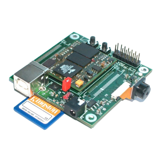
- Page 1 Hardware User Manual EVAL-BF5xx Board * SD-Card and Camera Module are not included in the EVAL-BF5xx package. www.tinyboards.com Maximum Power at Minimum Size...
- Page 2 Contact Bluetechnix Mechatronische Systeme GmbH Waidhausenstr. 3/19 A-1140 Vienna AUSTRIA/EUROPE office@bluetechnix.at http://www.bluetechnix.com http://www.tinyboards.com Version 2.0 2005-05-31 Document No.: 100-2022-01 Blackfin EVAL-BF5xx Hardware User Manual...
-
Page 3: Table Of Contents
Table of Contents Introduction ......................... 1 Overview........................1 Related Products ......................2 Specification ........................3 Functional Specification ....................3 Connectors, PCB Placement and PIN Assignment............4 2.2.1 P1 – USB Connector ....................4 2.2.2 P2 – Power Connector.................... 4 2.2.3 Px1 –... - Page 4 Bluetechnix takes no liability for any damages and errors causing of the usage of this board. The user of this board is responsible by himself for the functionality of his application. He is allowed to use the board only if he has the qualification.
-
Page 5: Introduction
1 Introduction The EVAL-BF5xx Board is a very low cost and lightweight evaluation platform for Bluetechnix core modules CM-BF533 and CM-BF561. The small baseboard has all hardware necessary to test the performance of the core modules including a high-speed serial port directly connectable to a computers USB port, a digital video camera interface and a SD-Card mass storage device socket. -
Page 6: Related Products
Power Supply The Camera Module as well as the SD-Card as shown on the cover page are not included in the EVAL-BF5xx Board. For the Camera Module the Kit-CAM-OV1 can be purchased from Bluetechnix. 1.2 Related Products CM-BF533: Blackfin DSP Processor Module powered by Analog Devices single core BF533 processor. -
Page 7: Specification
Bluetechnix www.tinyboards.com Maximum Power at Minimum Size 2 Specification 2.1 Functional Specification 60-pin : Data & Addr. Us, Mem. Control, (PPI2) Optional Power Connector Button Regulator USB Device Reset Connector CM-BF533 USB-UART OmniVision Converter 2V5 Voltage Camera CM-F561 UART Regulator... -
Page 8: Connectors, Pcb Placement And Pin Assignment
Bluetechnix www.tinyboards.com Maximum Power at Minimum Size 2.2 Connectors, PCB Placement and PIN Assignment Figure 2-2: Connector PCB Placement 2.2.1 P1 – USB Connector P1 is a standard USB-B Device Connector from which the board may draw its power of up to 500mA at most. -
Page 9: Px1 - Expansion Connector 1
Bluetechnix www.tinyboards.com Maximum Power at Minimum Size Signal Description Number +4V to +7V Input Supply Preferable 5V 2.2.3 Px1 – Expansion Connector 1 Pin 1 through Pin 60 of Px1 is connected directly to Pin 61 through Pin 120 of any Coremodule (CM). -
Page 10: Px2 - Expansion Connector 2
Bluetechnix www.tinyboards.com Maximum Power at Minimum Size 2.2.4 Px2 – Expansion Connector 2 Pin 1 through Pin 60 of Px2 is connected directly to Pin 1 through Pin 60 of any Coremodule. Part Baseboard Manufacturer Manufacturer ID Px1,Px2 177983-2 (female) or 177984-2 (male) -
Page 11: P6 - Jtag Connector
Bluetechnix www.tinyboards.com Maximum Power at Minimum Size HREF (NC) VSYNC (NC) PWDN (PPID10) PCLK (PPICLK) 2V5 VDD 3V3 DOVDD SIO_D (PPID9) CamClk (*) SIO_C (PPID8) Reset (GND) (*) Mount option R1/R5: Mount R1 for CM-BF533 clock source ; Mount R5 for CM- BF561 clock source 2.2.6 P6 –... -
Page 12: Mechanical Outline
Bluetechnix www.tinyboards.com Maximum Power at Minimum Size 2.3 Mechanical Outline Figure 2-3: Mechanical Outline – Expansion Connector Placement Blackfin EVAL-BF5xx Hardware User Manual Page 8... -
Page 13: Known Bugs
Bluetechnix www.tinyboards.com Maximum Power at Minimum Size 3 Known Bugs Blackfin EVAL-BF5xx Hardware User Manual Page 9... -
Page 14: Revision History
Bluetechnix www.tinyboards.com Maximum Power at Minimum Size 4 Revision History 2005-02-08 Release Version No. 1.0 Blackfin EVAL-BF5xx Hardware User Manual Page 10... -
Page 15: A List Of Figures And Tables
Bluetechnix www.tinyboards.com Maximum Power at Minimum Size List of Figures and Tables Figure 1-1: Overview of the EVAL-BF5xx Board ..............1 Figure 2-1: Detailed Block Diagram..................3 Figure 2-2: Connector PCB Placement ..................4 Figure 2-3: Mechanical Outline – Expansion Connector Placement ......... 8 Table 2-1: Connector Px1 pin assignment .................
Need help?
Do you have a question about the EVAL-BF5 Series and is the answer not in the manual?
Questions and answers