Table of Contents
Advertisement
Quick Links
The amplifier series is distributed with the CE mark, because they
are in accordance with the European Directives on EMC and Low
ELECTRICAL AND CONTROL EQUIPMENT CAN BE
DANGEROUS IF HANDLED IMPROPERLY
This manual describes the mechanical and electrical
characterists of the Microspeed series.
It is important, that the installation procedures are only performed
by qualified personnel in accordance with local safety guidelines.
Whoever installs the equipment must follow all of the technical
instructions printed in this manual.
For more information, please contact AXOR'S technical
department.
All rights reserved.Reproduction in whole or in part is prohibited without prior written
consent of the copyright owner.
All specifications are subject to change without prior notice.
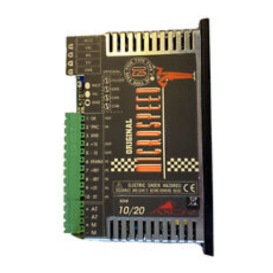
MICROSPEED
Voltage.
WARNING!
REV 04/05
English
1
Advertisement
Table of Contents

Subscribe to Our Youtube Channel
Related Manuals for Axor Microspeed 12


Summary of Contents for Axor Microspeed 12
- Page 1 Whoever installs the equipment must follow all of the technical instructions printed in this manual. For more information, please contact AXOR’S technical department. English All rights reserved.Reproduction in whole or in part is prohibited without prior written consent of the copyright owner.
-
Page 2: Table Of Contents
MICROSPEED REV 04/05 Index Chapter 1 1) Description 1.1 Introduction 1.2 Technical features 1.3 Inputs and outputs 1.4 Drive dimensions 2) Adjustments 2.1 Personalizations and settings 6 - 7 2.2 Solder bridges 2.3 Potentiometer adjustments 3) Diagnostic 3.1 L.E.D. indicators 4) Installation 4.1 Power supply rating 11-13... -
Page 3: Introduction
MICROSPEED REV 04/05 1.1 Introduction... -
Page 4: Technical Features
MICROSPEED REV 04/05 1.2 Tecnical Data Microspeed 12 9 - 28 Vdc* Microspeed 60 20 - 80 Vdc* Microspeed 110 30 - 130 Vdc* Sizes I Nom. (A) I Peak (A) +/- 1 +/- 2 2,5/5 +/- 2,5 +/- 5... -
Page 5: Inputs And Outputs
MICROSPEED REV 04/05 1.3 Inputs and Outputs Power terminals - AT Signal terminals 10 volts 4 mA m a x 10 volts 4 mA m a x... -
Page 6: Drive Dimensions
MICROSPEED REV 04/05 1.4 Drive dimensions 2.1 Personalizations and setting WARNING : After switching off to do the adjustments, please wait for about 30 sec before working inside the drive. - Page 7 MICROSPEED REV 04/05 RAMP SE SD SC Adjustment...
-
Page 8: Solder Bridges
MICROSPEED REV 04/05 2.2 Solder bridges J2 - J4 J5 - J6... -
Page 9: Potentiometer Adjustments
MICROSPEED REV 04/05 2.3 Potentiometer adjustment Pot. -
Page 10: Indicators
MICROSPEED REV 04/05 3.1 LED indicators Leds... -
Page 11: Power Supply Rating
MICROSPEED REV 04/05 4.1 Power supply rating WARNING:Use the following scheme and equation shown below to calculate the power supply rating. Trasformer Don’t use auto transformers. VOLTAGE : V1(ac) = Vmotor 0,9 x 1,36... - Page 12 MICROSPEED REV 04/05 Power supply rating (continued) C (mF) = P (VA) trasfo. x 2000...
- Page 13 MICROSPEED REV 04/05 Power supply rating (continued) Fusibili “slow” “slow” F 1° = P (VA) trasnf. V (primary) ac...
- Page 14 MICROSPEED REV 04/05 4.2 Instructions for EMC Requirements...
- Page 15 MICROSPEED REV 04/05 WARNING...
- Page 16 MICROSPEED REV 04/05 Filters Schaffner and Timonta...
- Page 17 MICROSPEED REV 04/05 I(A) = P tot 1.73 x V primary...
-
Page 18: Emc Requirements
MICROSPEED REV 04/05 EMC requirements M ax 0.5 m M ax 1m M ax 1m M a x 15m M icro sp ee d... - Page 19 MICROSPEED REV 04/05 Filters Electrical Characteristics Type Current Leakage Curr. Power loss Weight (mA) SCHAFFNER FN355 3(40°C) 0.07 (400V 50Hz) 0.55 SCHAFFNER FN2070 3(40°C) 0.4 (250V 50/60Hz) 0.55 TIMONTA FMW4 4(40°C) <0.5 (400V 50/60Hz) 1 TIMONTA FSS2 3(40°C) <0.5 (250V 50/60Hz) TIMONTA FSS2 6(40°C) <3 (250V 50/60Hz)
- Page 20 MICROSPEED REV 04/05 Filters The TIMONTA FMW65-4: The SCHAFFNER FN355-3: The TIMONTA FSS2-65-3 TIMONTA FSS2-65-6 The SCHAFFNER FN2070-3:...
-
Page 21: Connections
MICROSPEED REV 04/05 4.3 Connections Power connection... - Page 22 MICROSPEED REV 04/05 Connections...
- Page 23 MICROSPEED REV 04/05 Connections...
- Page 24 MICROSPEED REV 04/05 Connection...
-
Page 25: Initial Start Up
MICROSPEED REV 04/05 5.1 Initial start up W A R N I N G : C.N.C. WARNING:... - Page 26 MICROSPEED REV 04/05 Start up (continued) 6.0 Setting up the drive 6.1 Speed Adj. with tacho feedback...
-
Page 27: Nominal Current Adjustment
MICROSPEED REV 04/05 n° Vref Clockwise CounterClockwise 6.2 Nominal current adjustment cur rent express in... -
Page 28: Peak Current Adjustment
MICROSPEED REV 04/05 6.3 Peak current adjustment current express in 6.4 Offset adjustment made by tachogenerator feedback. -
Page 29: Ramp Time Adjustment
MICROSPEED REV 04/05 6.5 Ramp time adjustment J2 , J4 (closed). N O T E F U N C T I O N F U N C T I O N (RAMP res. ). The proper value is reported on the table (See note 2 ) Res. -
Page 30: Adjustment With Armature Feedback
MICROSPEED REV 04/05 6.6 Armature feedback adjustment RA resistor M C S 6 0 RA (k ohm) = 166 * Vref E - 1,4 * Vref M C S 1 1 0 RA (k ohm) = 159 * Vref E - 3 * Vref Example:Servom Vref E = 3000 x 20 = 60... - Page 31 MICROSPEED REV 04/05 RCA resistor RCA (k ohm) = 0,5 x n Ke Vref Ipk Ri Example: RCA (kohm) = 0,5 x 4000 x 50 =200 Kohm 10 x 20 x 2.5...
-
Page 32: Dynamic Costant Adjustment
MICROSPEED REV 04/05 6.7 Dynamic costant adjustment Usually,these calibrationsare made by the factory and don’t need adjusting. Only re-tuning by KV and DER potentiometer is required. “KV potentiometer” ”DER potentiometer” “DER p o t e n t i o m e t e r ”... - Page 33 MICROSPEED REV 04/05 “ K V potentiometer” “D er pot enti ome te r”,...
-
Page 34: Troubleshooting
MICROSPEED REV 04/05 7.0 Troubleshooting Warning... -
Page 35: Available Options
MICROSPEED REV 04/05 8.1 Options available Options External choke Caratteristiche e opzioni Microb plus N . B... -
Page 36: Encoder Feedback
MICROSPEED REV 04/05 8.2 Encoder feedback (option) Don’t exceed the load declared. - Page 37 MICROSPEED REV 04/05 Tecnical specification Encoder inputs Power supply levels Max. frequency Encoder power supply Max 75 mA Max.90 mA Operating temperature Terminals description C o d e D e s c r i p t i o n Pin out Solder bridge description C o d e D e s c r i p t i o n Standard...
- Page 38 MICROSPEED REV 04/05 Encoder adjustment Connections...
- Page 39 MICROSPEED REV 04/05...
-
Page 40: Limit Switch
MICROSPEED REV 04/05 8.3 Limit switch input (option) =+/- LIMIT SW. ENABLE =NOT ENABLE... - Page 41 MICROSPEED REV 04/05 Input and output M3 connector (option) Example of Limit Switch connection M3(option) Function: At opening one of the following contacts you disable the motor rotation in the corresponding direction.
-
Page 42: Pwm+Direction Command
MICROSPEED REV 04/05 8.4 Command with Pwm+Dir. (option) which must be able to elaborate the motor's speed ring Signal connector description Drive OK, Open Collector output 100mA Max. (Normally closed, opens when in protection mode). 3-12 GND Common zero signal Auxiliary output voltage +10V, 4mA. - Page 43 MICROSPEED REV 04/05 Note: On Pwm+Direction Product cover, the +REF, -REF identifications corrispond to, PWM and DIR inputs.
-
Page 44: Block Diagram
MICROSPEED REV 04/05 8.5 Block diagram...
Need help?
Do you have a question about the Microspeed 12 and is the answer not in the manual?
Questions and answers