Table of Contents
Advertisement
Quick Links
Advertisement
Table of Contents

Related Manuals for Axor MAGNUM 400


Summary of Contents for Axor MAGNUM 400
- Page 1 AXOR Industries Magnum400 ver.2 rel.05/'15 Service Manual...
- Page 2 All rights reserved. Reproduction in whole or in part is prohibited without prior written consent of the copyright owner. All specifications are subject to change without prior notification. This manual has been carefully checked. However, Axor does not assume liability for errors or inaccuracies. This manual conTains a descripTion of magnum400 and a guidelines for The drive's insTallaTion;...
-
Page 3: Table Of Contents
2.16 Emulated encoder outputs connection 2.17 Pulse/Dir inputs connections 2.18 Feedback signals connections 2.19 Multidrop connection 2.20 Canbus connection 2.21 RS485 connection 2.22 Magnum400 power up 2.23 Motor Test 3) diagnostic 3.1 Display 3.2 Alarms index conformity AXOR Industries Magnum400 ver.2 rel.05/'15 Service Manual... - Page 4 • Speeder One Interface • Positioner Manual • Display and Keypad Manual • Alarms Manual • ModBus Manual • CanOpen Reference Manual • Cables Manual • Oscilloscope Manual • Procedures Manual (available only on request) AXOR Industries Magnum400 ver.2 rel.05/'15 Service Manual...
-
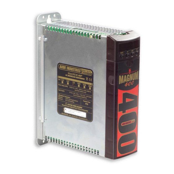
Page 5: Description 1.2 General View Magnum400
1) description chapter 1 description 1.1 Description 1.2 General view Magnum400 1.3 Technical Data 1.4 Mechanical Dimension 1.5 Product plate and Ordering Code AXOR Industries Magnum400 ver.2 rel.05/'15 Service Manual... -
Page 6: Description
The positioner can be managed via hardware (by using the digital inputs) or via RS232 (by using the Axor's Speeder One interface or another ModBus Master). It supports 32 programmable position profiles; a single task or a sequence posiTion conTrol of tasks are permitted. - Page 7 The communication between the drive and PC is done by a sofTware RS232 cable using the ModBUS protocol. standard inTerface The software works on the following operating systems: Windows 98, Windows 2000, Windows XP. AXOR Industries Magnum400 ver.2 rel.05/'15 Service Manual...
- Page 8 CBLS cable for motor feedback signal, encoder/resolver (meter multiple) optional CBLS power cable for motors series SuperSAX; motors series SuperSAX All optional features have to be requested by using the proper ordering code (see "1.5 Product plate and Ordering code"). AXOR Industries Magnum400 ver.2 rel.05/'15 Service Manual...
- Page 9 (m4 Connector) Main supply Display and KeyPad (m1 Connector) Encoder emulation, Pulse/Dir signals (m2 Connector) Analog and Digital Inputs/Outputs (j1 Connector) Encoder or Resolver signals (m5 Connector) Motor, brake and braking circuit connections AXOR Industries Magnum400 ver.2 rel.05/'15 Service Manual...
-
Page 10: Technical Data
1000W - 33Ohm +33Ohm 500W size: 1.5/3, 3.5/7, 7/14. 1000W - 66Ohm // 66Ohm 500W size: 10/20, 14/28, 20/40. 400vac 480vac set point values 695Vdc min ÷ 735Vdc max 815Vdc min ÷ 845Vdc max AXOR Industries Magnum400 ver.2 rel.05/'15 Service Manual... - Page 11 250kHz external protections (fuses or similar) Size 1,5/3 and 3,5/7 7/14 and 10/20 14/28 and 20/40 power supply (f T(Time Lag) 20A T auxiliary power supply (f external braking F(Fast) resistor (f AXOR Industries Magnum400 ver.2 rel.05/'15 Service Manual...
-
Page 12: Mechanical Dimension
MODE noTe: The m1 and m2 connectors are located under the plastic cover. To open it, push the cover on the borders (see A), move it down and remove it (see B). AXOR Industries Magnum400 ver.2 rel.05/'15 Service Manual... -
Page 13: Product Plate And Ordering Code
1= Present (opt) er = Encoder or Resolver (both) 0= Not Present (std) cBmd: canBus + multidrop interface r485: rs485 interface 1= Present (opt) 1= Present (opt) 0= Not Present (std) 0= Not Present (std) AXOR Industries Magnum400 ver.2 rel.05/'15 Service Manual... - Page 14 AXOR Industries Magnum400 ver.2 rel.05/'15 Service Manual...
-
Page 15: 2) Installation
2.15 Analog inputs connections 2.16 Emulated encoder outputs connection 2.17 Pulse/Dir inputs connections 2.18 Feedback signals connections 2.19 Multidrop connection 2.20 Canbus connection 2.21 RS485 connection 2.22 Magnum400 power up 2.23 Motor Test AXOR Industries Magnum400 ver.2 rel.05/'15 Service Manual... -
Page 16: General Advices
• if the drive is dirty: the cleaning is reserved to the producer; • if the fans are dirty: clean them by using a dry brush. disposal The disposal should be carried out by a certified company. AXOR Industries Magnum400 ver.2 rel.05/'15 Service Manual... - Page 17 The motor, as a result, is not controlled and can stop or go into neutral (for a time determined by the type of system). • During installation, avoid letting any residue with metallic components fall inside the drive. AXOR Industries Magnum400 ver.2 rel.05/'15...
- Page 18 Please remember that "leakage currents" must be considered when settings differential devices in order to avoid useless interventions. For safety reasons connect the prepared terminal to earth before powering the drive. Incorrect con- nections make filter operation unreliable. AXOR Industries Magnum400 ver.2 rel.05/'15 Service Manual...
-
Page 19: Positioning
Arrange the power components (converters, main's filters, resistors, terminals, ... ) in bins of the electrical panel different from those reserved to the command or control systems (PLC, PC, CNC, regulators, ...). This improves the level of immunity to interference of the system. AXOR Industries Magnum400 ver.2 rel.05/'15... -
Page 20: Environmental Conditions
• The electrical box must have suitably filtered air vents. Leave the necessary space both above and below the converters. • Periodically check drive case and fans for excess dust or dirt, that could interfere with the correct dissipation of the drive. AXOR Industries Magnum400 ver.2 rel.05/'15 Service Manual... -
Page 21: Cables
• Avoid crossing, overlapping and twisting cables together. If it is absolutely necessary to cross them, do so at 90°. • On request Axor provides motor signal cables series encoder or resolver for motors series Super- SAX. AXOR Industries Magnum400 ver.2 rel.05/'15... -
Page 22: Connection To Ground And Earth
It refers to the earth connection. It refers to the connection of the shield to the drive's carcass as illustrated on page It refers to the connection of the shield to the connector's metal ring. AXOR Industries Magnum400 ver.2 rel.05/'15... -
Page 23: Note About Cable Shielding
• drive side (20:50cm) remove the outside sheath and fix shield to the zinced pannel, by using a u-clamp (Axor's cables have incorporated u-clamp): • motor side the shield is internally connected to the metal ring of the motor connector, thus to earth through the motor's carcass. -
Page 24: Base Installation Procedure
2.7 Base installation procedure This procedure must be done only by qualified personel which are familiar with drives. if you need more information contact axor. a) power off all the supplies of the electrical box. b) Verify: the drive-motor coupling the stall current (I ) of the motor should be equal to/or greater than the nominal output current of the drive;... -
Page 25: Example Of Base Connection
2.8 Example of base connection Example of base connection: MAGNUM 400 SUB-D RS-232 9 pin DGT-OUT1 CAN BUS/RS485 OUT1-RTN J4/J3 Rj45 Cap 2.13 Cap 2.19, 2.20 and 2.21 DGT-OUT2 OUT2-RTN Motor CHA+ Feedback CHA- SUB-D CHB+ Cap 2.18 25 pin Cap 2.16... -
Page 26: Supply Connections
Pn= nominal power of each motor (VA), which can be calculated in this way: pn = n x cn / 9,55 Pn=nominal motor power (W) n= motor speed (rpm) Cn= motor nominal torque (Nm) AXOR Industries Magnum400 ver.2 rel.05/'15 Service Manual... -
Page 27: Motor Power Connection
The earth connection of the power cable’s shield must be made on the zinc-coated panel (using a u-clamp) near the drive (20-50cm). Motor side: the shield is connected to connector's metal ring, so it is connected to ground through motor's carcass. AXOR Industries Magnum400 ver.2 rel.05/'15 Service Manual... -
Page 28: Relè Ok And Regen Resistance Connections
If the cable length is greater than 20/30cm, it must be twisted and shielded. The shield must be connected to ground on both ends, utilising u-clamps to the zinced panel of the electrical box. AXOR Industries Magnum400 ver.2 rel.05/'15 Service Manual... - Page 29 • If the resistors are mounted externally, protect them. • Respect the following distances and shieldings: (mm) (mm) • Axor external resistances have the following dimensions: 260mm 35mm 400mm note: In accordance with the used resistance, internal or external, we recommend to correctly set the Regen Resistance parameter in the "General Setting"...
-
Page 30: Digital Inputs Connection
For a detailed description of the pre-programmed functions see enclosure "Speeder One Interface", "Additional Features Manual" and "Positioner Manual" on the CD provided with the drive. • Connect pin m2-13 (dgT-in rTn) to the ground bar of the system. AXOR Industries Magnum400 ver.2 rel.05/'15... -
Page 31: Digital Outputs Connections
This digital output can be used to send messages from the pre-programmed function of the drive. For a detailed description of the pre-programmed functions see enclosure "Speeder One Interface" on the CD provided with the drive. AXOR Industries Magnum400 ver.2 rel.05/'15... -
Page 32: Analog Outputs Connections
470n They can be set by the Speeder One interface. AGND CN-GND note: We suggest to connect the shield on both sides: drive side follow the indications illustrated on paragraph 2.6. AXOR Industries Magnum400 ver.2 rel.05/'15 Service Manual... -
Page 33: Analog Inputs Connections
The technical characteristics of TPRC input are as follows: Voltage: ±10v Max. Input impedance: 10k ohm. note: We suggest connecting the shield on both sides: drive side, follow the indications illustrated on paragraph 2.6. AXOR Industries Magnum400 ver.2 rel.05/'15 Service Manual... -
Page 34: Emulated Encoder Outputs Connection
CHZ- PGND CN-GND PGND common mode cn inputs Drive CHA- CHB- CHZ- PGND CN-GND PGND note: We suggest connecting the shield on both sides: drive side, follow the indications illustrated on paragraph 2.6. AXOR Industries Magnum400 ver.2 rel.05/'15 Service Manual... -
Page 35: Pulse/Dir Inputs Connections
+PULSE -PULSE 220 0_24V +24V 1/4 W 220 +DIR -DIR 220 0_24V note: We suggest to shield separatelly the couples of cable and to connect the shields together and to the PLC ground. AXOR Industries Magnum400 ver.2 rel.05/'15 Service Manual... - Page 36 2.17 Pulse/Dir inputs connections ElEctRical aXiS (GEaRiNG) connection MAGNUM400 MAGNUM400 (Slave) (Master) 220 220 220 220 PGND PGND note: We suggest connecting the shield on both sides: drive side, follow the indications illustrated on paragraph 2.6. AXOR Industries Magnum400 ver.2 rel.05/'15 Service Manual...
-
Page 37: Feedback Signals Connections
The ground connection of the external shield must Max 25m 20:50cm be made on the zinc-coated panel (using a u-clamp) near the drive (20-50cm). Drive Motor Motor side: the shield is connected to connector's metal ring. AXOR Industries Magnum400 ver.2 rel.05/'15 Service Manual... - Page 38 The ground connection of the external shield must Max 25m 20:50cm be made on the zinc-coated panel (using a u-clamp) near the drive (20-50cm). Drive Motor side: the shield is connected to connector's metal Motor ring. AXOR Industries Magnum400 ver.2 rel.05/'15 Service Manual...
-
Page 39: Multidrop Connection
1 and 2 of the j3 (or j4) connector of the last drive. • Axor drives use modBus communication protocol specified in the modicon instructions (see http://www.modicon.com/techpubs/). For more information see enclosure "modbus manual" on the CD provided with the drive. -
Page 40: Canbus Connection
CANL PGND PGND dc-dc Converter dc-dc Converter PGND note: Connect a resisTor (120 ohm, 1/4w) between pins 1 and 2 of the j3 (or j4) connector of the last magnum400 PGND dc-dc Converter AXOR Industries Magnum400 ver.2 rel.05/'15 Service Manual... -
Page 41: Rs485 Connection
MAGNUM400 2 PGND PGND dc-dc Converter dc-dc Converter PGND note: Connect a resisTor (120 ohm, 1/4w) between pins 4 and 5 of the j3 (or j4) connector of the last magnum400 PGND dc-dc Converter AXOR Industries Magnum400 ver.2 rel.05/'15 Service Manual... -
Page 42: Magnum400 Tm Power Up
DGT-IN1 input (D), in order to enable the INTERNAL ENABLE also. If the DGT- IN1 is not disabled then re-enabled, the +24V INTERNAL ENABLE remains disabled and AUXILIARY the user cannot execute any movement. SUPPLY MAIN SUPPLY AXOR Industries Magnum400 ver.2 rel.05/'15 Service Manual... -
Page 43: Motor Test
4) Open the Speeder One interface clicking on "Axormb.exe" executable file on directory: "C:\Programm\ Axor". The main window "axor servo drive" and the "select driver" windows open simultaneously. On the select driver window insert the drive's address (all drives have 1 set as default value), then click OK. - Page 44 (eventually contact Axor). 8) Connecting the load to the motor, it shoul be necessary to connect gains of speed loop, following this procedure: a- Set the "10: square wave"...
-
Page 45: 3) Diagnostic
3) diagnostic chapter 3 diagnostic 3.1 Display 3.2 Alarms AXOR Industries MAGNUM400 ver.2 rel.05/'15 Service Manual... -
Page 46: Display
This appears when there is the 24 up +24VDC auxiliary supply, but not the main supply. alxx There is alarm xx. The Safe Torque Off function is en- abled (the motor has not torque). AXOR Industries MAGNUM400 ver.2 rel.05/'15 Service Manual... -
Page 47: Alarms
Disable the drive, control the connections, reset This alarm comes on if one or more of the encoder the alarm, then enable the drive. channels are interrupted. If the alarm persists contact Axor. t drive alarm It is only a message. The internal I... - Page 48 Disable the drive, save new values, then Errors in reading/writing parameters on the Flash re-enable. If the problem persists contact Axor. al23 memory, or Flash memory is empty. This causes the opening of the Ok Relè contact and disables the drive's functionability.
- Page 49 This will generate Historical Alarm "AL32". And seb- al32 The speed value set in the drive was exceeded. sequently it will generate "AL31" which will initiate the Immediate Stop Function. AXOR Industries MAGNUM400 ver.2 rel.05/'15 Service Manual...
-
Page 50: Index
Example of base connection 25 Expansion cards 8 Fuse 11 General view 9 Holding brake 8 installation procedure 24 KeyPad 7 Maintenance 16 Mechanical Dimension 12 Motor holding brake 27 Motor power 27 Multidrop connection 39 AXOR Industries Magnum400 ver.2 rel.05/'15 Service Manual... - Page 51 Regen resistance 28 Rele' OK 28 resolver connection 38 Safety 8 black-out dynamic brake function 8 safety enable function 8 Security standard 16, 17, 18 Shielding 23 Speeder One 7 Storage 16 Transport 16 AXOR Industries Magnum400 ver.2 rel.05/'15 Service Manual...
-
Page 52: Conformity
In reference to noise immunity and noise emission the converters fulfil the requirement to the category second environment (industrial environment). If the installation of the drive is carried out differently than described in this manual, the user must carry out new measures to satisfy the requisites of law. AXOR Industries Magnum400 ver.2 rel.05/'15 Service Manual... - Page 53 AXOR Industries Magnum400 ver.2 rel.05/'15 Service Manual...
Need help?
Do you have a question about the MAGNUM 400 and is the answer not in the manual?
Questions and answers