Table of Contents
Advertisement
All manuals and user guides at all-guides.com
Mcs-Plus-gb Ver.21/02/2002
The MICROSPEED PLUS series of amplifiers are marked CE
because they conform to European Directives for
Electromagnetic Compatibility and Low Voltage.
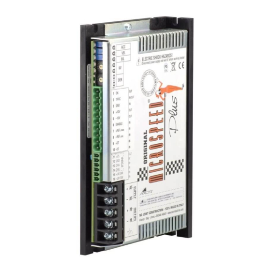
This manual describes the mechanical and electrical
characteristics of the Microspeed Plus servoamplifier series.
It is important that the installation procedures are only
performed by qualified personnel in accordance with local
safety guidelines.
Whoever installs the equipment must follow all of the
technical instructions printed in this manual.
For more information, please contact AXOR's technical
department.
Service Manual
MICROSPEED
Plus
1
Advertisement
Table of Contents

Subscribe to Our Youtube Channel
Related Manuals for Axor MICRO SPEED PLUS Series


Summary of Contents for Axor MICRO SPEED PLUS Series
- Page 1 It is important that the installation procedures are only performed by qualified personnel in accordance with local safety guidelines. Whoever installs the equipment must follow all of the technical instructions printed in this manual. For more information, please contact AXOR's technical department. Service Manual MICROSPEED Plus...
- Page 2 All manuals and user guides at all-guides.com Index Indice 1) Description 2) Indicator LEDs and Regulations 3) Installation Service Manual MICROSPEED Plus...
- Page 3 All manuals and user guides at all-guides.com Index 4) Start up procedures 5) Adjustments 6) Troubleshooting 7) Option Service Manual MICROSPEED Plus...
-
Page 4: General Description
All manuals and user guides at all-guides.com General Description 1.0 Security standards Danger Sign Installers must scrupulously adhere to prescribed directives and must communicate them to the users. Warning of Current being present Warning General Security Directives Along with what is prescribed in the manual, pay attention to the security directives for prevention of accidents and risks. - Page 5 All manuals and user guides at all-guides.com General Description Service Manual MICROSPEED Plus...
- Page 6 All manuals and user guides at all-guides.com General Description 1.1 Introduction Capitolo 1 Service Manual MICROSPEED Plus...
- Page 7 All manuals and user guides at all-guides.com General Description Characteristic and Options Service Manual MICROSPEED Plus...
-
Page 8: Technical Data
All manuals and user guides at all-guides.com General Description 1.2 Technical Data Microspeed 60 20 - 80 Vdc* Note a) Microspeed 140 40 - 180 Vdc* Microspeed 200 60 - 270 Vdc* Size I nom. (A) I peak(A) +/-1 +/-2 2.5/5 +/- 2.5 +/- 5... - Page 9 All manuals and user guides at all-guides.com General Description 1.3 Microspeed Plus Description Service Manual MICROSPEED Plus...
-
Page 10: Drive Dimensions
All manuals and user guides at all-guides.com General Description 1.4 Drive Dimensions A CC B IL D ER Service Manual MICROSPEED Plus... - Page 11 All manuals and user guides at all-guides.com General Description A CC B IL D ER Service Manual MICROSPEED Plus...
-
Page 12: Ordering Code
MCS PLUS Model: 060-140-200 Size: 01/02- 2.5/5 -06/12 -10/20 -14/28 -20/40 Heatsink: N=Normal, B=Booster Protection: S=Standard, T= Tropicalized 1000: Axor identification number Feedback: T0= Tachogenerator, A0=Armature, E0=Encoder Control mode: RD= Rifferential mode, I0= Demand current, PD=Pwm+Dir Service Manual MICROSPEED Plus... - Page 13 All manuals and user guides at all-guides.com General Description 1.6 Connections Service Manual MICROSPEED Plus...
-
Page 14: Signal Inputs And Outputs
All manuals and user guides at all-guides.com General Description 1.7 Signal inputs and outputs OK(OUT) TPRC(IN) A) Motor Current Limit Mode: Ving=10 x I required I peak B) Motor Current Limit Mode: Service Manual MICROSPEED Plus... - Page 15 All manuals and user guides at all-guides.com General Description C) Current Reference +10V(OUT) -10V(OUT) ENABLE(IN) +REF(IN) -REF(IN) +DT(IN) -DT(IN) Continued Service Manual MICROSPEED Plus...
- Page 16 All manuals and user guides at all-guides.com General Description 1.7a Signal inputs and outputs (6 poles) Note: The inputs 11-12-13-14, are enabled if the Encoder Option is present. +V(OUT) Power supply encoder (Optional) CHA(IN) (Optional) CHB(IN) (Optional) +LM SW (IN) Service Manual MICROSPEED Plus...
- Page 17 All manuals and user guides at all-guides.com General Description -LM SW (IN) 1.8 Power Supply Inputs and Outputs GROUND Service Manual MICROSPEED Plus...
- Page 18 All manuals and user guides at all-guides.com Adjustments 2.0 Potentiometer Adjustments Service Manual MICROSPEED Plus...
- Page 19 All manuals and user guides at all-guides.com Adjustments Continued Service Manual MICROSPEED Plus...
- Page 20 All manuals and user guides at all-guides.com Adjustments 2.1 Protections ----Reversible Protection Intervention: -Over Current limitation -Over/under voltage input Microspeed 60 20 Min 80 Max Microspeed 140 40 Min 180 Max Microspeed 200 57 Min 270 Max ----Irreversible Protection Intervention: -Short circuit -Over temperature -Missing or reversal tachogenerator/Encoder...
- Page 21 All manuals and user guides at all-guides.com Adjustments 2.2 L.E.D. indicators -OK (GREEN) Normally ON. - IN (RED) Normally OFF. - ST (RED) Normally OFF. - OC (RED) Normally OFF. - MD (RED) Normally OFF. Service Manual MICROSPEED Plus...
- Page 22 All manuals and user guides at all-guides.com Installation 3.0 Installation Notes • • • • • 3.1 Ventilation Service Manual MICROSPEED Plus...
- Page 23 All manuals and user guides at all-guides.com Installation MicroPower Plus Power Supply (optional) Service Manual MICROSPEED Plus...
-
Page 24: Installation
All manuals and user guides at all-guides.com Installation 3.2 Power Supply Construction and Rating WARNING:Use only Un-regulated power supplies with the Microspeed Plus Drive.The power supply is used to absorb the motor's BEMF. Als, with this scheme, no braking resistor are needed. Transformer: DO NOT USE AN AUTO TRANSFORMER... - Page 25 All manuals and user guides at all-guides.com Installation Voltage : V1(Dc) = VMotor 0,9x1.36 Service Manual MICROSPEED Plus...
- Page 26 All manuals and user guides at all-guides.com Installation Power Transformer: • • • • • POWER: If the power of a transformer exceeds a determined value, the inserted straightening point could be damaged in the enabling phase, due to overcurrent from the capacitors. •...
- Page 27 All manuals and user guides at all-guides.com Installation Discharge resistor Service Manual MICROSPEED Plus...
- Page 28 All manuals and user guides at all-guides.com Installation Fuses F 1 = (VA) trasformer x 1,1 Vac (primary) ac X MCS 2,5/5 =3,16A X MCS 5/10 X MCS 8/16 =10A X MCS 10/20 =16A X MCS 14/28 =20A X MCS 20/40 =25A Service Manual MICROSPEED...
-
Page 29: Multiple Connections
All manuals and user guides at all-guides.com Installation 3.3 Multiple Connections DIRECTLY I n c o r r e c t W i r i n g Technique Use This Service Manual MICROSPEED Plus... - Page 30 All manuals and user guides at all-guides.com Installation 3.4 Ground and Shield Connections Service Manual MICROSPEED Plus...
- Page 31 All manuals and user guides at all-guides.com Installation Service Manual MICROSPEED Plus...
- Page 32 All manuals and user guides at all-guides.com Installation 3.5 Instructions for EMC Requirements Network Filters Service Manual MICROSPEED Plus...
- Page 33 All manuals and user guides at all-guides.com Installation Instructions for EMC requirements (continued) I(A) = P tot 1.73 x V primary Continued Service Manual MICROSPEED Plus...
- Page 34 All manuals and user guides at all-guides.com Installation Instructions for EMC requirements (continued) Mechanical and Electrical Characteristics Type Current Leakage Curr. Power loss Weight (mA) SCHAFFNER FN355 3(40°C) 0.07 (400V 50Hz) 0.55 SCHAFFNER FN2070 3(40°C) 0.4 (250V 50/60Hz) 0.55 TIMONTA FMW4 4(40°C) <0.5 (400V 50/60Hz) 1 TIMONTA FSS2 3(40°C) <0.5 (250V 50/60Hz)
- Page 35 All manuals and user guides at all-guides.com Installation Instructions for EMC requirements (continued) The TIMONTA FSS2-65-3 TIMONTA FSS2-65-6 The SCHAFFNER FN2070-3: Mechanical dimension Service Manual MICROSPEED Plus...
- Page 36 All manuals and user guides at all-guides.com Installation 3.6 Examples of Microspeed Plus Connections Do Not Service Manual MICROSPEED Plus...
- Page 37 All manuals and user guides at all-guides.com Installation 3.7 Common Mode Reference Service Manual MICROSPEED Plus...
- Page 38 All manuals and user guides at all-guides.com Installation 3.8 Current Reference (Torque Mode) Ving =10 x I request 10 x 9 = 3,2V I pk MCS In this case the loop of internal velocity automatically excludes itself . Service Manual MICROSPEED Plus...
- Page 39 All manuals and user guides at all-guides.com Installation 3.9 Current Output Limitation only positive In this case the loop of internal velocity remains active. Service Manual MICROSPEED Plus...
- Page 40 All manuals and user guides at all-guides.com Installation 3.9a Current Output Limitation (continued) In this case the loop of internal velocity remains active. Service Manual MICROSPEED Plus...
-
Page 41: Limit Switch Input
All manuals and user guides at all-guides.com Installation 3.10 Limit Switch Input +/- =NOT ENABLE =+/- LIMIT SW. ENABLE Service Manual MICROSPEED Plus... - Page 42 All manuals and user guides at all-guides.com Installation 3.11 Power Connections Service Manual MICROSPEED Plus...
- Page 43 All manuals and user guides at all-guides.com Start up procedures 4.0 Preliminary Checks • • • How to proceed • • What to check 4.1 Starting Procedures • • Service Manual MICROSPEED Plus...
-
Page 44: Start-Up Procedures
All manuals and user guides at all-guides.com Start up procedures • • • • • Service Manual MICROSPEED Plus... - Page 45 All manuals and user guides at all-guides.com Adjustments 5.0 Personalizazion and Settings Soldering points Personalization base adjustments Service Manual MICROSPEED Plus...
- Page 46 All manuals and user guides at all-guides.com Adjustments 5.1 Adjustement components Service Manual MICROSPEED Plus...
- Page 47 All manuals and user guides at all-guides.com Adjustments Adjustement components (Continued) Service Manual MICROSPEED Plus...
-
Page 48: Solder Bridges
All manuals and user guides at all-guides.com Adjustments 5.2 Solder Bridges 17 Solder Bridges 1 2 3 4 5 6 7 8 9 10 11 12 13 14 15 16 17 S2- S4 Service Manual MICROSPEED Plus... - Page 49 All manuals and user guides at all-guides.com Adjustments S14 -S15 S16- S17 Note: Closed only for Pwm+Dir Optional. NOTE: Further along in the manual all desired speed feedback are highlighted the soldering points to close. Service Manual MICROSPEED Plus...
- Page 50 All manuals and user guides at all-guides.com Adjustments 5.3 Speed adjustment with tacho feedback n° Vref Clockwise CounterClockwise Service Manual MICROSPEED Plus...
- Page 51 All manuals and user guides at all-guides.com Adjustments 5.4 Speed adjustment with Armature feedback S7 Closed, S12 open, RA resistor MCS PLUS 60 RA (k ohm) = 166 x Vref E - 1,4 Vref MCS PLUS 140 RA (k ohm) = 159 x Vref E - 3,3 Vref MCS PLUS 200...
- Page 52 All manuals and user guides at all-guides.com Adjustments 5.4 Speed adjustment with Armature feedback RCA resistor RCA (k ohm) = 0,5 x n Ke Vref Ipk Ri Example: RCA (kohm) = 0,5 x 4000 x 50 =200 Kohm 10 x 20 x 2.5 5.5 Adjusting Speed Balance (Offset) Service Manual MICROSPEED...
- Page 53 All manuals and user guides at all-guides.com Adjustments 5.6 Nominal and Peak Current Adjustment Nominal Current Peak Current Service Manual MICROSPEED Plus...
-
Page 54: Ramp Time Adjustment
All manuals and user guides at all-guides.com Adjustments 5.7 Ramp time Adjustment S2, S4 (closed). (RAMP) FUNCTION RANGE NOTE Res. RAMP 680K 820K 1MOHM TIME 0,2-2,6 Sec. 0,3-3,2 Sec. 0,4-3,9Sec Service Manual MICROSPEED Plus... - Page 55 All manuals and user guides at all-guides.com Adjustments 5.8 Dynamic Constant Adjustments dinamiche Usually, these settings are made by the factory and do not need to be changed. Only re-tuning by KV and DER potentiometer is required. “KV potentiometer” ”DER potentiometer” “DER and KV potentiometers”...
- Page 56 All manuals and user guides at all-guides.com Adjustments 5.8 Dynamic Constant Adjustments (Continue) "KV potentiometer" "Der potentiometer" Caution Service Manual MICROSPEED Plus...
- Page 57 All manuals and user guides at all-guides.com Troubleshooting 6.0 Troubleshooting Service Manual MICROSPEED Plus...
-
Page 58: Encoder Feedback
All manuals and user guides at all-guides.com Options 7.1 Encoder Feedback (option) Don’t exceed the load declared. Tecnical specification Encoder inputs Power supply levels Max. frequency Encoder power supply Max 220 mA Max.220 mA Operating temperature Terminals description Code Description Pin out Solder bridge description Code Description... - Page 59 All manuals and user guides at all-guides.com Options Encoder Connections Service Manual MICROSPEED Plus...
- Page 60 All manuals and user guides at all-guides.com Option Encoder Connection from External Power Supply Service Manual MICROSPEED Plus...
- Page 61 All manuals and user guides at all-guides.com Option Speed Adjustment with Encoder Feedback Service Manual MICROSPEED Plus...
- Page 62 All manuals and user guides at all-guides.com Option 7.2 Command with PWM + Direction (Option) which must be able to elaborate the motor's speed ring Service Manual MICROSPEED Plus...
- Page 63 All manuals and user guides at all-guides.com Option Signal Connector Description. Note: -The other pins connector are N.C -For the leds indicator, in this option,see Chapter 2.2 -The only active adjustemente in this option are RIN and RIP. -If closed S16 or S17 you insert for PWM and DIR input a pull-up resistor of 3.3 Kohm to internal +14V.
-
Page 64: Ce Conformity Declaration
All manuals and user guides at all-guides.com CE CONFORMITY DECLARATION The manufacturer: AXOR Industries Address: Via Cà Sordis 6/g, 36054 Montebello Vicentino (VI) ITALY DECLARE under their own responsability that the following line of products: MICROSPEED PLUS with the relative options and accessories...
Need help?
Do you have a question about the MICRO SPEED PLUS Series and is the answer not in the manual?
Questions and answers