
Related Manuals for Foss EyeFoss


Summary of Contents for Foss EyeFoss
- Page 1 EyeFoss™ User Manual 6007 2981 / Rev. 10 Copyright 2010 / All rights reserved FOSS Analytical A/S, Foss Allé 1, DK-3400 Hillerød, Denmark Tel Int +45 7010 3370, Fax +45 7010 3371, E-mail info foss.dk...
- Page 2 EyeFoss™ All information is liable to change without prior notice. For latest information about documentation updates for your specific instrument, please contact your local FOSS representative.. Rev. Date of Issue Revised Material 2010-06-22 First edition 2013-07-12 General update 2014-11-20 Genereal update...
-
Page 3: Table Of Contents
Start Button ..............2:5 2.3.4 A Kernel’s Way Through an Analysis ......2:6 2.3.5 2.3.6 Protection Cap ..............2:7 EyeFoss™ Software ............. 2:8 Installation............Operating Instructions ........Getting Started .............. 4:1 Foss Integrator Start-up ..........4:1 Installing a License ............4:2 Importing a Prediction Model ........ - Page 4 Use of Other Templates ..........4:30 4.11 Creating a New User ...........4:35 4.12 Mosaic Connection .............4:38 Mosaic Settings .............4:39 4.12.1 4.13 EyeFoss Simple UI ............4:42 4.13.1 Launching SimpleUI ............4:42 Using SimpleUI ..............4:44 4.13.2 Closing SimpleUI ............4:45 4.13.3 Maintenance ............EyeFoss Maintenance ...........5:1 5.1.1...
- Page 5 EyeFoss™ Performance Data ............8:2 Legal Data ..............8:2 PC Requirements ............8:2 User Manual 6007 2981 / Rev. 10...
- Page 6 EyeFoss™ User Manual 6007 2981 / Rev. 10...
-
Page 7: General
Warning Unpacking, assembly and installation of the instrument should be performed by a FOSS authorised service engineer. Warning The instrument is NOT to be operated in atmospheres which could constitute an explosion risk. -
Page 8: Laser
1.2.2 Laser The EyeFoss is a Class I laser product and contains a laser. The laser is totally shielded by the cabinet, and there is no risk of laser radiation during normal use. The embedded laser is a Class 3B laser with the specifications: •... -
Page 9: Product Safety
Caution The system may only be repaired by personnel certified by FOSS. FOSS recommends the use of original FOSS spare parts. If spare parts from other are used, the warranty no longer applies. -
Page 10: Disposal Instructions
• the product has not been used for purposes other than those reasonably contemplated by FOSS • the product has not been altered or repaired with non-original FOSS parts or by personnel not authorised by FOSS • only original FOSS consumables and accessories or equivalents recommended by FOSS have been used •... -
Page 11: Copyright Of Embedded Software
EyeFoss™ listed in the User Manual and/or in the FOSS product software and in the Owner's Guide. The liability for worn down parts subject to wear is limited to cases with extraordinary wear due to defective material or production errors. - Page 12 EyeFoss™ User Manual 6007 2981 / Rev. 10...
-
Page 13: Introduction
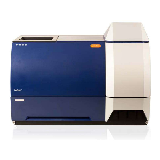
EyeFoss™ Introduction General This manual will take you through the routine operation of the EyeFoss™ instrument and its functions. It will also give guidance for the routine maintenance to secure accurate analysis and ensure a long instrument life. Image Analysis During the growth period and harvest grain is affected by factors such as weather, soil, growth location, harvest conditions, fungi, insects etc. - Page 14 EyeFoss™ Fig. 2:1 EyeFoss™ LED On/Off Drawer Hopper Belt brush Feeder Unit Camera Unit Conveyor belt Start button User Manual 6007 2981 / Rev. 10...
-
Page 15: System Description
PC and may be printed if a printer is connected. The electronic and optical parts of EyeFoss are assembled in a sealed chassis and can therefore be placed in a dusty or humid environment. The analysis is automatic and calibrated through known references. -
Page 16: System Overview
EyeFoss™ 2.3.2 System Overview The main parts of the EyeFoss are: Fig. 2:3 System Overview Hopper Prediction engine Feeder External PC Conveyor belt Drawer Camera 2.3.3 Functional Description Normal Analysis The sample is poured via the hopper (1) to the feeder (2). -
Page 17: Start Button
4.5. 2.3.4 Start Button In the upper right corner of the EyeFoss is a start button. It indicates which process is on-going. Fig. 2:4 Start button In the table below the different indications of the start button are explained. -
Page 18: A Kernel's Way Through An Analysis
Wild Oat Wheat healthy The prediction engine sends the result of the evaluation and the composed image to Foss Integrator for display on The unknown kernel gets classified in the external computer. order to the pre-installed component settings. The ones viewed here are only a selection of a number of components that exist. -
Page 19: Protection Cap
EyeFoss™ 2.3.6 Protection Cap Warning Make sure that there is no gap between the protection cap and the metal sheet by securing the screw as the laser reflection can be hazardous to the operator. Ef025a Fig. 2:6 The protection cap must close the gap... -
Page 20: Eyefoss™ Software
EyeFoss™ EyeFoss™ Software EyeFoss can only be operated via the external PC and the program Foss Integrator (FI). For information on how to use this program, see chapter 4 "Operating Instructions". User Interface For daily work the FI will start up with the Report window. -
Page 21: Installation
EyeFoss™ Installation Warning Unpacking, assembly and installation of the instrument should be performed by a FOSS authorised service engineer. Caution The air circulation around the cooling flange must not be inhibited. Leave uncovered with sufficient space for air circulation at all times. - Page 22 EyeFoss™ User Manual 6007 2981 / Rev. 10...
-
Page 23: Operating Instructions
Either general help or help about the current view. The F1 key can also be used to access help to the current view. Note: Foss Integrator is also used for other instruments so some images and products shown in the help files may not be related to image analysis or grain. -
Page 24: Installing A License
Initially the user name is “DefaultManager” and the password is “1” but they can be changed by setting up a new user (see section 4.11). Fig. 4:3 Different parts of Foss Integrator can be accessed from the Window menu in the toolbar. Installing a License A license must be installed to run Foss Integrator and the calibrations. - Page 25 EyeFoss™ Click on Licenses..Fig. 4:6 This will open the window License Registration where you can see the licenses that are already installed. Click on the Add... button to add new licenses. Fig. 4:7 User Manual 6007 2981 / Rev. 10...
-
Page 26: Importing A Prediction Model
C:\FOSS\FossIntegrator\PredictionModels\ or they can downloaded through Mosaic. Once the prediction models have been copied to this directory, start Foss Integrator. Below is described how to import a prediction model locally. Go to Foss Integrator [Settings] and select Prediction Model Settings Fig. - Page 27 EyeFoss™ Click on New. Fig. 4:10 Select “Instrument” in the drop-down menu Type and select the prediction model that you want to import. Fig. 4:11 Click OK and the prediction model will synchronise with the instrument. Fig. 4:12 User Manual 6007 2981 / Rev. 10...
- Page 28 EyeFoss™ Select one of the prediction models in the Prediction Model Settings window and click on Properties..Fig. 4:13 A new window appears with a number of tabs. The most important tabs are Image Transfer and Slope and Intercept. Here is it possible to select what has to be transferred/saved and make changes to slope and intercept on the predictions.
-
Page 29: Setting Up A Product
Setting Up a Product To set up a product, a prediction model must first be in made and set up (see above). In the Foss Integrator window, select Product Settings. Fig. 4:16 Click in the area to the left in the Product Settings window. - Page 30 EyeFoss™ Right-click and select New..If the instrument is connected to Mosaic, the product will already be here under the Network tab. Fig. 4:17 Enter a name and a description and click OK. Fig. 4:18 Click the Edit button next to “Job types” (pos. 1 in Fig. 4:19).
- Page 31 EyeFoss™ For a normal sample it should be like in Fig. 4:19 (multiple selection of “Normal”, “Normal Single Kernel” and “Calibration”). Click the button Change under “Icon”. Select an icon for the product and click Open. Fig. 4:20 Select icon Select Released for routine analysis under “Status”.
- Page 32 EyeFoss™ 11. Click Add... in the menu at the bottom. Fig. 4:22 12. Select the prediction model(s) that you want and click OK. Fig. 4:23 The other options now become selectable on the lower part of the window. 13. Click Secondary..
- Page 33 EyeFoss™ 14. Select all the “secondary” prediction models in the popup window and click OK. Fig. 4:25 Secondary prediction models decide which results are displayed. If you don’t select any here, they will not appear in the result view. The Product Settings window will now look like Fig. 4:26 below.
-
Page 34: Creating Quick Job For Single Kernals Anaylsis
EyeFoss™ 4.5.1 Creating Quick Job for Single Kernals Anaylsis Go to Foss Integrator [Settings] and select Product Settings. Fig. 4:27 Click Edit... under to “Job types” in the centre of the Product Settings window. Select “Normal Single Kernal” (and none of the others). - Page 35 The other options now become selectable on the lower part. Click Secondary..Fig. 4:30 Select all the “secondary” prediction models in the popup window. Fig. 4:31 Click OK and return to the Foss Integrator Results window. User Manual 6007 2981 / Rev. 10 4:13...
- Page 36 EyeFoss™ 10. Click on the Create quick job. Fig. 4:32 11. Select “Advanced” and click OK. Fig. 4:33 12. Select the job that was created earlier and give it a suitable name. Fig. 4:34 4:14 User Manual 6007 2981 / Rev. 10...
-
Page 37: Making A Zero Setting (Calibration)
As no prediction model is used during the Zero setting, any prediction model will be fine, but there must be a prediction model and it must be set up in the correct way. Go to Foss Integrator [Settings] and select Product Settings similar to setting up a normal product. - Page 38 EyeFoss™ Give it the name “Zero” and add a short description. Fig. 4:37 Click Edit... next to “Job types” in the middle of the window. Select job type “Zero-setting” and click OK. Fig. 4:38 Click the button Change under “Icon”.
- Page 39 It can be any prediction model since it is not used for the calibration. However, a prediction model must exist to be able to run it. Fig. 4:41 10. Click OK and return to the Foss Integrator Results window. User Manual 6007 2981 / Rev. 10 4:17...
- Page 40 EyeFoss™ 11. Click on the option Create quick job. Fig. 4:42 12. Select “Advanced” and click OK. (If you are making a normal Quick job, then select “Simple” instead). Fig. 4:43 13. In the Quick job Creation - Advanced window and tick the check box Auto start.
-
Page 41: Running A Self-Test
Below is described how to do it manually. Go to the Diagnostic view in Foss Integrator and right-click on the instrument icon (“Prediction PC Active”) in the lower left corner. Click on Self Test.. -
Page 42: Viewing Or Printing The Diagnostic Report
Double click on the latest PDF file to open the diagnostics report. In the report can you then see the warnings and errors, depending on the problem and either correct it yourself or contact a FOSS representative. 4:20 User Manual 6007 2981 / Rev. 10... -
Page 43: Explaination Of The Diagnostic Report
EyeFoss™ Fig. 4:48 Select Diagnostic report 4.7.2 Explaination of the Diagnostic Report The name of the diagnostic report is made up in the following way: Diag_ date _time _ chassie number_ followed by either “Pass” or “Fail” (for example “Diag_2017- 05-02 22-10-58_8388616_13917861_Pass.pdf”) - see Fig. - Page 44 Geo Stripe (2D plate) shows the results of checks of black and white patterns. For correction of errors please call a FOSS service technician. Validation stripe ( 2D plate) shows the results of checks for dirt on the 2D plate.
-
Page 45: Analysing A Sample
EyeFoss™ Graphs The belt profiles shown in the graphs are the same as in the summary table. They are used for additional information and to find the root cause of the warnings. Images of 2D Calibration Targets The gray images at the end of the report are mainly for experts and can be difficult to interpret. - Page 46 EyeFoss™ Double-click on the box next to the sample ID (see figure below). Fig. 4:55 Enter a sample id in the Sample ID area in the window that appears and click Fig. 4:56 There are also other options in this window but none of them can be edited. They are only for information.
-
Page 47: Multiple Samples
EyeFoss™ 4.8.2 Multiple Samples If multiple samples are going to be analysed using the same product /prediction model, you can setup jobs so the analyse button on the instrument can be used to start the analysis. This method is more simple if many analyses are to be done using the same product. - Page 48 EyeFoss™ Click on Add to joblist and it will be added as a new job. Start the analysis immediately by clicking Start Now or later by closing the window and using the start button on the instrument. When a sample is ready, the instrument will ask for the next sample.
-
Page 49: Editing Sample Information
EyeFoss™ Editing Sample Information When the sample is ready, a box for the sample id will appear in the result window. Double-click in the box under ID Fig. 4:61 Enter a sample id in the Sample ID area in the window that appears Fig. -
Page 50: 4.10 Exporting Result
EyeFoss™ 4.10 Exporting Result Depending how the prediction models /products are set up, results can be saved in two ways: • Either only the results will be saved • or results and images. Usually, images will not be saved since each sample takes up a lot of disk space. - Page 51 EyeFoss™ Select a CSV file and results. Fig. 4:65 Export as CSX User Manual 6007 2981 / Rev. 10 4:29...
-
Page 52: 4.10.1 Use Of Other Templates
EyeFoss™ 4.10.1 Use of Other Templates Click on Report Profile Settings in the Foss Integrator window if you want to use other templates Fig. 4:66 This will open the Report Profile Settings window. Click New to make a new report profile. - Page 53 EyeFoss™ Click Add to get access to the prediction models you can choose. Fig. 4:69 Select the prediction model it should be active for and click OK. Fig. 4:70 User Manual 6007 2981 / Rev. 10 4:31...
- Page 54 EyeFoss™ Click Secondary to get access to selecting secondary models. Fig. 4:71 Select the secondary models you wish to use and click OK. Fig. 4:72 4:32 User Manual 6007 2981 / Rev. 10...
- Page 55 EyeFoss™ Select one of the available reports in the Report template dropdown list and click Next >. If you need other formats, please contact FOSS. Fig. 4:73 Select an output format for the report and click Next >. Fig. 4:74 User Manual 6007 2981 / Rev.
- Page 56 EyeFoss™ 10. Select an installed printer in dropdown list. Fig. 4:75 11. Click on Finish to return to the initial screen. Fig. 4:76 12. Click OK and the report profile is ready for use. 4:34 User Manual 6007 2981 / Rev. 10...
-
Page 57: 4.11 Creating A New User
13. The selected results will be printed, so it can be either one or multiple results. Fig. 4:77 4.11 Creating a New User Go to Foss Integrator [Settings] and select User Manager. Fig. 4:78 User Manual 6007 2981 / Rev. 10... - Page 58 EyeFoss™ This will open a the User Manager window. Fig. 4:79 User Manager main window Right-click on Users and select New. Fig. 4:80 This will open the User properties window. 4:36 User Manual 6007 2981 / Rev. 10...
- Page 59 EyeFoss™ Fill in information about the user.Leave Member of empty for now. Fig. 4:81 User Properties window Click OK. Right-click on Operators under Groups and select Add member... to add the user to a group. Fig. 4:82 This will open the Group properties - Operators window.
- Page 60 The use of Mosaic is not described here. Either use help files in Mosaic or a FOSS training course for help and education on how to use the Mosaic network tool.
-
Page 61: 4.12.1 Mosaic Settings
EyeFoss™ 4.12.1 Mosaic Settings Go to Foss Integrator [Settings] and select the Mosaic synchronisation. Fig. 4:85 This will open the Mosaic Synchronisation. Already Connected to Mosaic Clicking the Sync button to make a new synchronisation Fig. 4:86 User Manual 6007 2981 / Rev. 10... - Page 62 EyeFoss™ The Synchronisation Log will then be updated. Fig. 4:87 Not Connected to Mosaic Go to the Settings tab to set up the synchronisation for the first time. Fig. 4:88 Mosaic Synchronisation window - not filled in 4:40 User Manual 6007 2981 / Rev. 10...
- Page 63 Enter the Mosaic server address and the port number for the server. This information may be different from instrument to instrument. Consult your network manager or a FOSS representative to get the correct address and port number (see Fig. 4:89 below).
-
Page 64: 4.13.1 Launching Simpleui
From "SimpleUI" it is not possible to rename the Sample ID, nor to see previously analysed samples. 4.13.1 Launching SimpleUI Start Foss Integrator by clicking the icon on the desktop. For details about the start-up of Foss Integrator, see section 4.2. Fig. 4:90 Start SimpleUI by clicking the icon on the desktop. - Page 65 Go to the LIMS Monitor 1 tab. In the dropdown list below Connection, select the SimpleUI. The exact name of the SimpleUI is specified during the installation of EyeFoss and can vary from instrument to instrument. Click Connect. Fig. 4:93 LIMS monitor 1 tab Tick Remote control active in the bottom of the tab.
-
Page 66: 4.13.2 Using Simpleui
Go to the Main LIMS monitor tab. Click on Enable LIMS. Fig. 4:95 Main LIMS monitor tab 10. Go to "SimpleUI" interface and click OK. SimpleUI can now be used to control EyeFoss. 4.13.2 Using SimpleUI E F 028a Fig. 4:96... -
Page 67: 4.13.3 Closing Simpleui
The error/warning icon (pos 2 in Fig. 4:96) flashes red/yellow when an event occurs, which requires attentions. To see the error/warning message, go to Foss Integrator and select Work Session Events in the Window menu in Foss Integrator. 4.13.3 Closing SimpleUI... - Page 68 EyeFoss™ 4:46 User Manual 6007 2981 / Rev. 10...
-
Page 69: Eyefoss Maintenance
EyeFoss™ Maintenance EyeFoss Maintenance 5.1.1 General For the instrument to work properly a daily, weekly and annual service should be made. Daily and weekly maintenance are done by the operator of the instrument. Annual maintenance is performed by a qualified service engineer. - Page 70 EyeFoss™ Warning Risk of getting jammed when cleaning the conveyor belt. Open the hood of the instrument. Loosen the two thumb screws on the conveyor belt cover and lift the cover out. EF004b Fig. 5:2 Removal of the conveyor belt cover Use a 13 mm box spanner to loosen the bolt and rotate the belt stretcher counter clockwise so the belt becomes loose.
-
Page 71: Cleaning / Replacement Of Belt Brush
EyeFoss™ Fig. 5:4 Cleaning/exchange of conveyor belt Note: Do not use any sharp tools. The belt surface must remain a blue colour. Reassemble in reverse order. When putting the belt back, make sure it is correctly located in the centre of the guiding rollers. -
Page 72: Cleaning Of Anti-Static Brush
EyeFoss™ 5.1.4 Cleaning of Anti-Static Brush Upon cleaning the belt brush or replacement of the belt, the anti-static brush should also be cleaned in order to remove excess material that accumulates in it. This is not prompted by the Clean procedure. -
Page 73: Replacement Of Filter
EyeFoss™ Gently pull out the fuse holder to its maximum and remove the blown fuses. Fig. 5:7 Power supply connection Replace the T 4AL 250TP fuses in the fuse holder and gently put the holder back in place. 5.1.6 Replacement of Filter The filter that is located on the rear of the instrument should be replaced regularly, approximately once a year. -
Page 74: Software Maintenance
EyeFoss™ Fig. 5:9 Replacement of filter Replace the filter and re-assemble in reverse order. 5.1.7 Software Maintenance Since the analysis generates much data, some care should be taken to the computer system. Results can be saved on a network drive, but on a weekly basis it is recommended to make a backup and cleanup the database. - Page 75 EyeFoss™ “Backup” and “Restore” are self explaining. “Cleanup” will delete old results. Fig. 5:12 Click on Cleanup and older data will be delated. Fig. 5:13 User Manual 6007 2981 / Rev. 10...
-
Page 76: Foss Service Visit
Contact your local FOSS representative for yearly maintenance. FOSS offers a wide range of local support products and training adapted to your market requirements. Please contact the local FOSS representative for a tailor-made package to fit your specific needs. -
Page 77: Foss Integrator Troubleshooting
6.1.1 At Startup If you try to start Foss Integrator when an instance is already running, or if Foss Integrator was closed in unexpected way, the following error message may appear. Fig. 6:1 6.1.2... -
Page 78: In Foss Integrator
EyeFoss™ 6.1.3 In Foss Integrator Common errors in Foss Integrator are shown in the lower left corner of the screen. Fig. 6:3 All warnings have a yellow indicator to the left and errors a red indicator. An explanation of the warning or error can be seen in the Description column. If you double-click on a description, a window will popup with further information about the warning or error and a hint on how to solve the problem. -
Page 79: Module Problems
In most cases a shutdown and a restart are required. Communication Errors Communication between EyeFoss and the PC is done via Local Area Network (LAN) connection. The status of the connection is visible in the notification area of the lower right corner of the PC-screen. - Page 80 EyeFoss™ Communication problems can be caused by improper settings in the PC (e.g. Firewall restrictions; TCP/IP protocol settings etc.). Normally, this is corrected by the FOSS representative during the first installation. Please contact a FOSS representative if communication problems occur (e.g. after installation of a new PC or after changes to the PC's network configuration).
-
Page 81: Parts, Accessories And Consumables
EyeFoss™ Parts, Accessories and Consumables See the Owner’s Guide (distribured via USB). User Manual 6007 2981 / Rev. 10... - Page 82 EyeFoss™ User Manual 6007 2981 / Rev. 10...
-
Page 83: Technical Specifications
EyeFoss™ Technical Specifications Technical Data ™ EyeFoss Dimensions Depth = 620 mm Height = 490 mm Width = 660 mm Weight 50 kg External fuses T 4AL 250TP Rated current 2.0 A (100 V) 0.8 A (240 V) Power consumption... - Page 84 EyeFoss™ Performance Data ™ EyeFoss Measurement mode Reflectance Imagingand volumetric scanning Illumination type Diffused light from high-power light emitting diodes. Illumination wavelengths 410, 465, 525, 590, 630, 850 nm (UV, Blue, Green, Amber, Red, NIR). 3-D profiling Triangulation based laser 3 D scanning...
Need help?
Do you have a question about the EyeFoss and is the answer not in the manual?
Questions and answers