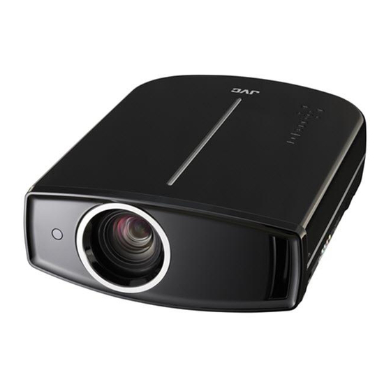
Download Print this page

Advertisement

SERVICE MANUAL
2010
4 S ERVICE MANUAL
PA037<Rev.001>
DLA-HD550-BU, DLA-HD550-BC,
DLA-HD550-BE, DLA-HD550-WE,
DLA-HD950-BU, DLA-HD950-BC,
DLA-HD950-BE, DLA-HD990-BU,
for DLA-HD950/HD990
COPYRIGHT © 2010 Victor Company of Japan, Limited
1
PRECAUTION. . . . . . . . . . . . . . . . . . . . . . . . . . . . . . . . . . . . . . . . . . . . . . . . . . . . . . . . . . . . . . . . . . . . . . . . . 1-4
2
SPECIFIC SERVICE INSTRUCTIONS . . . . . . . . . . . . . . . . . . . . . . . . . . . . . . . . . . . . . . . . . . . . . . . . . . . . . . 1-6
3
DISASSEMBLY . . . . . . . . . . . . . . . . . . . . . . . . . . . . . . . . . . . . . . . . . . . . . . . . . . . . . . . . . . . . . . . . . . . . . . 1-14
4
ADJUSTMENT . . . . . . . . . . . . . . . . . . . . . . . . . . . . . . . . . . . . . . . . . . . . . . . . . . . . . . . . . . . . . . . . . . . . . . . 1-19
5
TROUBLESHOOTING . . . . . . . . . . . . . . . . . . . . . . . . . . . . . . . . . . . . . . . . . . . . . . . . . . . . . . . . . . . . . . . . . 1-22
D-ILA PROJECTOR
DLA-HD990-BE

TABLE OF CONTENTS

COPYRIGHT © 2010 Victor Company of Japan, Limited
No.PA037<Rev.001>
2010/4

Advertisement

loading

Summary of Contents for JVC DLA-HD550-BU

  • Page 1: Table Of Contents

    SERVICE MANUAL D-ILA PROJECTOR PA037<Rev.001> 2010 4 S ERVICE MANUAL DLA-HD550-BU, DLA-HD550-BC, DLA-HD550-BE, DLA-HD550-WE, DLA-HD950-BU, DLA-HD950-BC, DLA-HD950-BE, DLA-HD990-BU, DLA-HD990-BE for DLA-HD950/HD990 COPYRIGHT © 2010 Victor Company of Japan, Limited TABLE OF CONTENTS PRECAUTION............... . . 1-4 SPECIFIC SERVICE INSTRUCTIONS .
  • Page 2 SPECIFICATION Item DLA-HD950/DLA-HD990 DLA-HD550 Product Name D-ILA Projector Model Name DLA-HD950 / DLA-HD990 DLA-HD550 Display Panel/Size D-ILA device*1 *2 /0.7" (1920pixels x 1080pixels) x 3 (Total no. of pixels: Approx. 6.22million) Projection Lens 2.0 x power zoom lens (1.4:1 to 2.8:1)(Zoom/Focus: Power) Light-source Lamp 200 W Ultra-high pressure mercury lamp [Part No.
  • Page 3 PC compatible signals HDMI Designation Resolution Dot CLK Polarity Total No. Total No. No. of No. of [kHz] [Hz] [MHz] of dots of lines effective dots effective lines [dot] [line] [dot] [line] 1 VGA 60 640 X 480 31.500 60.000 25.200 - 2 VGA 59.94 640 X 480...
  • Page 4: Precaution

    SECTION 1 PRECAUTION Safety Precautions (1) This design of this product contains special hardware and voltmeter. many circuits and components specially for safety purpos- Move the resistor connection to each exposed metal es. For continued protection, no changes should be made part, particularly any exposed metal part having a return to the original design unless authorized in writing by the path to the chassis, and measure the AC voltage across...
  • Page 5 Preventing static electricity Electrostatic discharge (ESD), which occurs when static electricity stored in the body, fabric, etc. is discharged, can destroy the laser diode in the traverse unit (optical pickup). Take care to prevent this when performing repairs. 1.5.1 Grounding to prevent damage by static electricity Static electricity in the work area can destroy the optical pickup (laser diode) in devices such as laser products.
  • Page 6: Specific Service Instructions

    Recreating the quality of film in movie theaters with every nu- Clear Motion Drive technology successfully generates an ac- ance reproduced was what JVC had in mind when we curate intermediate frame even for images with fast-moving equipped our D-ILA front projector models with original picture action by employing a high-precision interpolation algorithm modes.
  • Page 7 DIFFERENCE POINT ITEM DLA-HD550-B DLA-HD550-W DLA-HD950-B DLA-HD990-B Body Color Black White Black Black ← Contrast 30,000:1 50,000:1 70,000:1 ← ← Brightness 1000lm 900lm ← ← Lens aperture 3 steps 16 steps ← ← Color management Used ← ← THX display standard Used ←...
  • Page 8 2.3.2 OPERATION BUTTON & LED LOCATION Light on (Red): Light on (Red): Standby mode Warning mode WARNING Light on (Green): LAMP During projection Light on/Blinking (Orange): Lamp warning Blinking (Green): STANDBY/ON Image is temporarily hidden Blinking (Red): To turn on/off the power Cool Down mode To switch input INPUT...
  • Page 9 LAMP UNIT INSTRUCTIONS 2.4.4 Lamp use time reset • Be sure to reset the Lamp use time after replacing the lamp Refer to the INSTRUCTIONS for a detailed operating descrip- unit. Unless reset, the projector will cease operation (lamp will tion.
  • Page 10 SERVICE POLICY Support the repair of each PCB/Block PCB name/Block name Parts number Method for repair PROCESSOR PWB (DLA-HD550) PC0072011U9 Unit exchange PROCESSOR PWB (DLA-HD950/DLA-HD990) PC0072014U9 Unit exchange POWER PWB PC0072013U9 Unit exchange FAN CONTROL PWB SXT-3502A Unit exchange TEMP. SENSOR PWB PC0065264U9 Unit exchange LAMP COVER SW PWB...
  • Page 11 SERVICE MENU 2.7.2 Release The service menu contains items not ordinarily needed by the Press the [MENU] button to exit the menu indication. user. 2.7.3 Basic operation Use these as necessary during service. Use the following buttons to operate the service menu. (1) Choose the SETTING MENU with the [ / ] button.
  • Page 12 2.7.4 SETTING ITEMS Item Adjustment range Initial value Function Model Only the display Display of model name Main Only the display Display of Main CPU software version Only the display Display of Sub CPU software version Only the display Display of DD program version LOCATION Only the display Color Temp.
  • Page 13 PICTURE MODE INITIAL SETTING VALUE [DLA-HD550] Natural Cinema 1 Cinema 2 Cinema3 Stage Dynamic User1/User2 Contrast Brightness Color Tint Color Temp 6500K 5800K 6500K 7500K 7500K High Bright 6500K Gamma Normal Normal Sharpness Detail Enhance Lens Aperture Clear Motion Drive High High High...
  • Page 14: Disassembly

    SECTION 3 DISASSEMBLY Main body (Used figure are DLA-HD550-BE) 3.1.1 Removing the Lamp cover and Lamp unit (See Fig.1, (2) Remove the two screws D attaching the both side of the Top cabinet. (See Fig.4) (1) Remove the two screws A Attachiing the Lamp cover. (See (3) Disengage four hooks a engaged both side of the Top cab- Fig.1) inet.
  • Page 15 3.1.4 Removing the Ground plate (See Fig.7, 8, 9) (2) Disconnect the connector wire from main body connected (1) Remove the twelve screws G attaching the Ground plate. to connector of the IP PWB. (See Fig.11) (3) Disconnect the connector wires from Front cover connect- ed to connectors CN1906 CN1907...
  • Page 16 (2) Disconnect the each connector wires from Power supply PWB and then remove the five screws N attaching the Power supply PWB. (See Fig.16) Fig.13 (2) Disconnect the each connectors from Power supply PWB and then remove the three screws L attaching the Fan con- Fig.16 trol PWB.
  • Page 17 3.1.10 Removing the Optical block (See Fig.20, 21, 22) 3.1.11 Removing the Air duct (Upper) (See Fig.23) (1) Removing the two screws U attaching the Balast PWB cov- (1) Remove the seven screws X attaching the Air duct (Up- er. (See Fig.20) per).
  • Page 18 3.1.14 Removing the Air duct (Lower) (See Fig.26) 3.1.17 Removing the Thermostat (See Fig.28) (1) Remove the six screws AA and two screws BB attaching (1) Remove the two screws DD attaching the Thermostat. the Air duct (Lower). Fig.28 3.1.18 Removing the AC inlet (See Fig.29) (1) Remove the four screws EE attaching the AC inlet.
  • Page 19: Adjustment

    SECTION 4 ADJUSTMENT BEFORE STARTING ADJUSTMENT INSTRUMENTS AND TOOLS (1) Adjustment items utilize a personal computer. • Oscilloscope (2) Data back up is required before adjustments. • Light meter [for example: Minolta T-10] (3) Allow the equipment and test instruments adequate time •...
  • Page 20 ADJUSTMENT PROCEDURE 4.4.3 CMS DATA BACKUP Instruments Scaler Service Software REPLACING COMPONENTS Test point PROCESSOR Adjustment menu Preparation Note : Keep the power ON during the operation. ADJUSTMENT (1) Run Scaler Service Software. (2) Select Com Port, click [Connect to FPJ] to connect the PC and the projector.
  • Page 21 4.4.5 COLOR TEMPERATURE Instruments Color meter(CL- REPLACING 200),Signal generator COMPONENTS PROCESSOR Test point Adjustment menu Service menu <Adjust> → <Color temperature> OPTICAL BLOCK Preparation Set lining has been exe- cuted (more than 10 min- utes) ADJUSTMENT (1) Set CL-200 approximately in the center of the image, facing the projector.
  • Page 22: Troubleshooting

    SECTION 5 TROUBLESHOOTING PROTECTIVE SENSOR AND PROTECTIVE SWITCH In event of abnormal operation due to circuit or component failure, setting error or other reason, in order to prevent serious damage to the set and preserve the integrity of peripheral equipment, sensors and switches are provided for protective functions. Cooling is conducted at the same time a corresponding LED flashes (about 90 seconds).
  • Page 23 ERROR LOG (SELF-DIAGONOSIS RECORD AND INDICATION) 5.3.1 Outline By using the special setting and adjustment software, data related to abnormal operation (history) stored in the projector can be load. On the basis of contents "LED (INDICATOR) WARNING INDICATONS" set and lamp use time, internal and external temperature, and ther data prior to the previous usage time can be viewed as a table.
  • Page 24 MCU FIRMWARE UPDATE 5.5.3 INSTALLATION OF DRIVER (1) Set the projector to UP DATE mode.(While pressing Stand- Please carry out the backup of ROM data before the repair of by/On button, then plug the power cord) ALL LED are light- the projector, the adjustment by all means.
  • Page 25 (8) The following message is displayed and click "Continue 5.5.4 HOW TO USE THE UPDATE TOOL Anyway" button. (1) Set the projector to UP DATE mode.(While pressing Stand- by/On button, then plug the power cord) ALL LED are light- (2) Open the [ILA-FPJ Updater] from the start menu. (3) The following screen is displayed, click "Browse"...
  • Page 26 (12) Disconnect the USB cable. (13) Return a projector to a standby mode. (All LED flashes on and off for 60 seconds when push [Standby/On] of the key- pad and shift to a standby mode. (14) The following messages are displayed when it fail in up- date.
  • Page 27 (No.PA037<Rev.001>)1-27...
  • Page 28 Victor Company of Japan, Limited Digital Imaging Products Business Division Projector Operation 12, 3-chome, Moriya-cho, Kanagawa-ku, Yokohama-city, Kanagawa-prefecture, 221-8528, Japan (No.PA037<Rev.001>) Printed in Japan...