Table of Contents
Advertisement
Available languages
Available languages
Model#
SKU#
67536-0508D2 1001-407-752
INSTALLATION AND CARE GUIDE
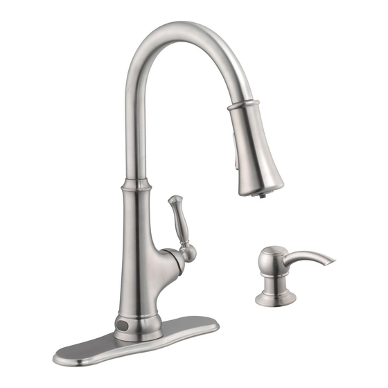
PULL-DOWN KITCHEN FAUCET
Questions, problems, missing parts?
Before returning to the store, call Glacier Bay Customer Service
8 a.m. - 7 p.m., EST, Monday - Friday
9 a.m. - 6 p.m., EST, Saturday
1-855-HD-GLACIER (1-855-434-5224)
HOMEDEPOT.COM/GLACIERBAY
THANK YOU
We appreciate the trust and con dence you have placed in Glacier Bay through the purchase of this kitchen
faucet. We strive to continually create quality products designed to enhance your home. Visit us online to see
our full line of products available for your home improvement needs. Thank you for choosing Glacier Bay!
THD
07/2015 REV.01
Advertisement
Chapters
Table of Contents

Subscribe to Our Youtube Channel
Related Manuals for Glacier bay 67536-0508D2


Summary of Contents for Glacier bay 67536-0508D2
- Page 1 HOMEDEPOT.COM/GLACIERBAY THANK YOU We appreciate the trust and con dence you have placed in Glacier Bay through the purchase of this kitchen faucet. We strive to continually create quality products designed to enhance your home. Visit us online to see our full line of products available for your home improvement needs.
-
Page 2: Table Of Contents
Glacier Bay products are manufactured with superior quality standards and workmanship and are backed by our limited lifetime warranty. Glacier Bay products are warranted to the original consumer purchaser to be free of defects in materials or workmanship. We will replace FREE OF CHARGE any product or parts that proves defective. -
Page 3: Package Contents
Pre-Installation (continued) PACKAGE CONTENTS Sensor Control Box Soap Pump Assembly Part Description Quantity Part Description Quantity Faucet body Weight Rubber washer Quick connect assembly Metal washer Sensor control box Protective cap Battery pack "AA" Battery Wrench Soap pump Escutcheon Soap assembly Bolt Gasket Soap dispenser... -
Page 4: Installation
Installation Installing the faucet assembly Installing the escutcheon CAUTION: Always turn off the water supply before NOTE: This step is for escutcheon installation (optional). removing an existing faucet or replacing any part of a If the escutcheon will not be used, install the faucet faucet. - Page 5 Installation (continued) Installing the faucet assembly Securing the faucet assembly □ Install the rubber washer (B) and metal washer (C) NOTE: This step is for escutcheon installation (optional). onto the threaded shank. If the escutcheon will not be used, install the faucet assembly as described in step 1.
- Page 6 Installation (continued) Installing the protective cap Installing the pulldown hose □ □ Screw the protective cap (E) onto the threaded Before installing the hose (K), ensure that the mounting shank (1). protective cap (1) is on the end of the hose (K). □...
- Page 7 Installation (continued) Installing the sensor cable NOTE: The side of the control box (O) with "in" and "out" showing must face the front of the cabinet (away from the back of the cabinet). □ Install the data cable (1) to the control box connection (2). Ensure the arrows on the data cable (3) and the control box connection (4) are aligned to one another to ensure proper installation.
- Page 8 Installation (continued) Installing the batteries NOTE: This step is for batteries installation (optional). If the batteries will not be used, install as described in step 12. □ To open the battery housing, squeeze the sides while pulling the cover (1). DO NOT pull on the wire. See g 1.
- Page 9 Installation (continued) Installation using the battery pack NOTE: This step is for battery installation (optional). If the battery will not be used, install as described in step 12. □ Insert the battery pack cable (1) into the control box connection (2). NOTE: After installing the battery pack, the light on the sensor will ash and the faucet will sound when you move your hand in the sensor area.
- Page 10 Installation (continued) Placing the battery pack into the battery pack seat NOTE: This step is for battery installation (optional). If the batteries will not be used, skip to step 12. Before installation, select the location for the battery pack seat (1) and verify that the battery pack (P) will reach battery pack seat (1).
- Page 11 Installation (continued) Installation using the AC Attaching the quick connector adapter (not included) to the receiving block □ Connect the hose with the yellow tag to the hose NOTE: This step is for installation without batteries using an AC adapter (not included). If using the batteries, install on the control box (O) with a matching yellow tag.
- Page 12 Installation (continued) Installing the weight □ Install the weight clip (L) at the point of the hose (K) marking “weight here”. □ Insert the weight (M) onto the clip (L) by sliding it down onto the clip (L). Installing the soap dispenser □...
-
Page 13: Operation
Installation (continued) Making the water supply connections NOTE: The hot side inlet tube is indicated by a label. Avoid twisting wires together or placing the wires close to each other and damaging. □ Thread the nut (1) on the supply line onto the outlet of the water supply valve (2) and tighten with a wrench. -
Page 14: Care And Cleaning
Operation (continued) Operating the sensor min. NOTE: The sensor is active only when the handle is in the ON position. □ Turn the handle (1) to the full on position, activating the sensor (2) and turning the water on. □ To turn the water off, move your hand within the sensor range (8in. -
Page 15: Troubleshooting
Troubleshooting Water will not shut off when The light on the sensor is turning the handle to the OFF flashing continuously position □ If the handle is closed, turn the handle to the on position and move your hand in the sensor □... - Page 16 Reassemble the connector and hose. Hose Connector Washer Control □ This indicates that the control box is damaged. Call Glacier Bay customer service to request a replacement control box. Replace the old control box with the new control box.
-
Page 17: Service Parts
Service Parts Faucet ID tags can be found on the hot water inlet Part Description Part Number Part Description Part Number Spray head and Hose RP38223* Quick connect RP70482 assembly Wearable ring RP70380 O-ring RP60071 O-ring RP60089 Cartridge RP20005 Weight clip RP64204 Bonnet nut RP70394... - Page 18 Questions, problems, missing parts? Before returning to the store, call Glacier Bay Customer Service 8 a.m. - 7 p.m., EST, Monday - Friday 9 a.m. - 6 p.m., EST, Saturday 1-855-HD-GLACIER (1-855-434-5224) HOMEDEPOT.COM/GLACIERBAY Retain this manual for future use.
- Page 19 HOMEDEPOT.COM/GLACIERBAY GRACIAS Agradecemos la con anza que has depositado en Glacier Bay al comprar este grifo para cocina. Nos esforzamos por crear continuamente productos de calidad diseñados para mejorar tu hogar. Visítanos en Internet para ver nuestra línea completa de productos disponibles para las necesidades de mejoras de tu hogar. ¡Gracias por...
-
Page 20: Información Importante
GARANTÍA LIMITADA DE POR VIDA Los productos de Glacier Bay están fabricados con normas y mano de obra de calidad superior y están respaldados por nuestra garantía de por vida limitada. Glacier Bay garantiza al comprador consumidor original que sus productos no presentan defectos materiales o de fabricación. -
Page 21: Contenido Del Paquete
Pre-instalación (continuación) CONTENIDO DEL PAQUETE Caja de control del sensor Ensamblaje de la bomba para jabón Pieza Descripción Cantidad Pieza Descripción Cantidad Cuerpo del grifo Peso Arandela de goma Ensamblaje del conector rápido Arandela metálica Tuerca Caja de control del sensor Tapa protectora Llave Paquete de baterías... -
Page 22: Instalación
Instalación Cómo instalar el ensamblaje Cómo instalar la placa del grifo protectora PRECAUCIÓN: Cierra siempre el suministro de agua NOTA: Este paso es para la instalación de la placa antes de quitar un grifo existente o reemplazar cualquier protectora (opcional). Si no usarás la placa protectora, pieza de un grifo. - Page 23 Instalación (continuación) Cómo instalar el ensamblaje Cómo fijar el ensamblaje del del grifo grifo □ Instala la arandela de goma (B) y la arandela de NOTA: Este paso es para la instalación de la placa metal (C) en el vástago roscado. protectora (opcional).
- Page 24 Instalación (continuación) Cómo instalar la tapa Cómo instalar la manguera protectora retráctil □ □ Enrosca la tapa protectora (E) en el vástago de Antes de instalar la manguera (K), asegúrate de montaje roscado (1). que la tapa protectora (1) esté en el extremo de la manguera (K).
- Page 25 Instalación (continuación) Cómo instalar el cable del sensor NOTA: El lateral de la caja de control (O) con las indicaciones “adentro” (“in“) y “afuera” (“out“) debe estar hacia el frente del gabinete (alejado de la parte posterior de este). □ Instala el cable de datos (1) en la conexión de la caja de control (2).
- Page 26 Instalación (continuación) Cómo instalar las baterías NOTA: Este paso es para la instalación con baterías (opcional). Si no usas baterías, realiza la instalación como se describe en el paso 12. □ Para abrir el compartimento de la batería. Aprieta las partes laterales mientras halas la cubierta (1). NO hales por el cable.
- Page 27 Instalación (continuación) Instalación usando las baterías NOTA: Este paso es para la instalación con baterías (opcional). Si no usas baterías, realiza la instalación como se describe en el paso 12. □ Inserta el cable del paquete de las baterías (1) en la conexión de la caja de control (2). NOTA: Después de instalar las baterías, la luz del sensor parpadeará...
- Page 28 Instalación (continuación) Cómo colocar las baterías en su base NOTA: Este paso es para la instalación con baterías (opcional). Si no se van a usar baterías, continúa con el paso 12. Antes de la instalación, selecciona el lugar para la base de las baterías (1) y veri ca que el paquete de baterías (P) alcanzará...
- Page 29 Instalación (continuación) Instalación usando el Cómo montar el conector Adaptador CA (no incluido) rápido al bloque receptor NOTA: Este paso es para la instalación sin baterías □ Conecta la manguera con la etiqueta amarilla con usando un adaptador CA (no incluido). Si usas las baterías, la manguera de la caja de control (O) que tiene una instala como se indica en el paso 9 y salta al paso 13.
- Page 30 Instalación (continuación) Instalar la peso □ Instala el sujetador de la peso (L) en la punta de la manguera (K) marcada “weight here” (peso aquí). □ Inserta la peso (M) en el sujetador (L) deslizándola en el sujetador (L). Cómo instalar el dispensador de jabón □...
-
Page 31: Funcionamiento
Instalación (continuación) Cómo hacer las conexiones del suministro de agua NOTA: El tubo de entrada del agua caliente se identi ca con una etiqueta. Evita enroscar los cables juntos o colocarlos cerca y evita dañarlos. □ Enrosca la tuerca (1) de la línea de suministro en la salida de la válvula de suministro de agua (2) y aprieta con una llave. -
Page 32: Cuidado Y Limpieza
Funcionamiento (continuación) Cómo poner en funcionamiento el sensor min. NOTA: Es sensor se activa únicamente cuando la manija está en la posición abierta (ON). □ Gira la manija (1) completamente a la posición abierta para activar el sensor (2) y abrir el ujo de agua. -
Page 33: Solución De Problemas
Solución de problemas El suministro de agua no se La luz del sensor parpadea detendrá al mover la manija a constantemente la posición cerrada (OFF). □ Si la manija está cerrada, muévela a la posición abierta y mueve la mano en el área del sensor. □... - Page 34 Arandela Caja de control □ Esto indica que la caja de control está dañada. Llama al servicio al cliente de Glacier Bay para solicitar el reemplazo de la caja de control. Reemplaza la caja de control vieja por la nueva.
-
Page 35: Piezas De Repuesto
Piezas de repuesto Las etiquetas de identi cación de la mezcladora pueden encontrarse en la entrada de agua caliente. Pieza Descripción Número de pieza Pieza Descripción Número de pieza Ensamblaje del Cabezal rociador y RP38223* RP70482 manguera conector rápido Anillo de uso RP70380 Aro tórico RP60089... - Page 36 ¿Problemas, preguntas o piezas faltantes? Antes de regresar a la tienda, llama al servicio al cliente de Glacier Bay de lunes a viernes entre 8 a.m. y 7 p.m. y los sábados entre 9 a.m. y 6 p.m.(hora estándar del Este) 1-855-HD-GLACIER (1-855-434-5224) HOMEDEPOT.COM/GLACIERBAY...
Need help?
Do you have a question about the 67536-0508D2 and is the answer not in the manual?
Questions and answers