
Related Manuals for Apollo AAN-32

Summary of Contents for Apollo AAN-32
- Page 1 AAN-32 Hardware Manual Revision Date: 26 OCT 2011 This manual contains confidential information and may only be reproduced or distributed with the written consent of Apollo Security Sales, Inc. © 2011 Apollo Security Inc.
- Page 2 Apollo Security, Inc. While every precaution has been taken in the preparation of this document, Apollo Security assumes no responsibility for errors or omissions, or for damages resulting from the use of information contained in this document or from the use of programs and source code that may accompany it.
- Page 3 IMPORTANT INFORMATION W A R N I N G HIGH VOLTAGE, AC MAIN POWER SHOULD ONLY BE CONNECTED BY QUALIFIED, LICENSED ELECTRICIANS. ALL APPLICABLE LAWS AND CODES MUST BE FOLLOWED. IF THIS PRECAUTION IS NOT OBSERVED, PERSONAL INJURY OR DEATH COULD OCCUR Power should not be applied to the system until after the installation has been completed.
-
Page 4: Table Of Contents
Serial ................................. Network ................................. ANI-1 ..............................Hardware Layout ............................Jumpers ............................24 RJ-45 Jack ............................24 Host Interface Connector ............................24 LEDs ............................25 ANI-100 ..............................Introduction ............................Hardware Layout ............................DIP Switches ............................26 © 2011 Apollo Security Inc. - Page 5 ................................. Telnet ................................. 2 ANI-100 Communication Configuration ........................... 42 3 Firmware Upgrading ........................... 45 Part V Memory Capacity Part VI Specifications Part VII Supplemental Figures Part VIII Table of Figures Part IX Revision History Index © 2011 Apollo Security Inc.
-
Page 6: Part I Introduction
Part Introduction... -
Page 7: Overview
AAN-32’s internal memory and does not rely on a constant connection to the host computer. Downloadable field devices are available as well that do not require constant connection to the controller to maintain functionality (e.g. -
Page 8: General Features
AAN-32 Hardware Manual General Features · Supports up to 32 card readers (either directly to intelligent card readers, or via Apollo AIM/API reader interfaces) · Up to 65,000 Cardholders or 25,000 Events with 2 MB of RAM · Supports Input to Relay linking across field devices ·... -
Page 9: Programming Host
AAN-32. Once programmed, the AAN-32 will continue to function without connection to the host. A record of all actions that happen while there is no connection is stored in the memory of the AAN (limited by the capacity of the memory) for reporting at a later time when connection with the host has been re-established. - Page 10 Part Hardware Layout...
-
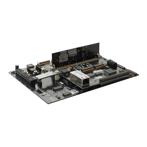
Page 11: Part Ii Hardware Layout
Terminal Connectors The AAN-32 has one terminal block for connecting power, alarm inputs, and connection to field device lines. The connection terminals are factory equipped with removable screw-down quick connectors which are easily removed from the board by firmly grasping the connector and pulling away from the board. If pliers are used to remove the connectors, they should be of the rubber-tipped type. - Page 12 Host Port Connection Transmit Data (+) (Port 3) Transmit Data (-) Signal Ground Receive Data (+) Receive Data (-) Device Port Connection Transmit Data (+) (Port 4) Transmit Data (-) Signal Ground Table 2.1 AAN-32 Terminal Connections. © 2011 Apollo Security Inc.
-
Page 13: Dip Switches
DIP Switches The AAN-32 has two blocks of DIP switches, with 8 switches in each block. These switches are used to set various configuration options for the panel. The switches of SW1 are used for configuring the baud rate of device ports 3-6, and remain constant. -
Page 14: Dip Switch Tables
SW2 controls internal settings for the panel including host communication and operation mode. 2.2.1 DIP Switch Tables Port 4 Baud Rate Port 3 Baud Rate Switch # 1200 2400 9600 57.6K (port 3 only, not used on port 4) © 2011 Apollo Security Inc. - Page 15 Duplex Note: SW1 positions 1-4 are not used. With ANI-1 installed SW2 position 6 is not used. With no ANI-1 SW2 positions 6-8 are not used. Table 2.1: DIP Switch Settings for SW1 and SW2 © 2011 Apollo Security Inc.
-
Page 16: Dip Switch Function
Do not use force greater than gentle pressure when installing any components. Refer to the figure for the exact location of these connectors. The connectors are also labeled on the AAN-32 in white lettering on the circuit board. © 2011 Apollo Security Inc. -
Page 17: Device Port Communication Sockets
Memory Backup Battery Connection: J1 In the case of total power failure, the memory of the AAN-32 will be stored for up to 6 months (in basic configuration) by power supplied by 3 AA (LR6) size batteries. A battery holder with connector is supplied with the AAN. -
Page 18: Simm Memory Sockets
SIMM Memory Module Socket: J9 The AAN-32 has one 72-pin socket which can contain either a AME-10 (1MB, part number 430-150) or AME-20 (2MB, part number 430-160) module, for a maximum 2 MB of storage of card codes and events. -
Page 19: Leds
Hardware Layout LEDs The AAN-32 has 3 LEDs for use in monitoring functioning of panel and for diagnosis of problems. The LEDs function in two modes: startup, and normal operation. Refer to the figure for exact location of the LEDs. The LEDs are also labeled on the circuit board with white lettering. -
Page 20: Additional Installation Information
AAN-32 Hardware Manual Additional Installation Information © 2011 Apollo Security Inc. -
Page 21: Mounting Holes
Hardware Layout 2.6.1 Mounting Holes Four holes are provided for mounting the AAN-32 (see Part 7: Supplemental Drawings for scale drawings showing the exact location of the holes). © 2011 Apollo Security Inc. - Page 22 AAN-32 Hardware Manual © 2011 Apollo Security Inc.
- Page 23 Hardware Layout Figure .1 AAN-100 Mounting Holes. Location of mounting holes for the AAN-100 is shown in scale. Note that the drawing will not print the exact size of the actual circuit board. © 2011 Apollo Security Inc.
- Page 24 Part System Wiring...
-
Page 25: Part Iii System Wiring
Power Power is supplied to the AAN-32 by the voltage connection in the main terminal block (see Part 2.1 for exact locations of terminals). The power connection should be 12-28 VDC. Power consumption is 300 mA with ASI-1 and 400 mA with ANI-1. -
Page 26: Grounding System
Thus, all system events are protected and will not be sent to a host that is not ‘ listening’, therefore losing events. The connection can be made either by serial connection (using Port 3) or, in the case of the AAN-32-NCC, by Ethernet (using ANI-1 or ANI-100 Network Interface Module). -
Page 27: Serial
3.3.1 Serial Using Port 3, the connection from the AAN-32 to the host can be made using RS-232 or RS-485 protocols. The choice to use RS-232 or RS-485 depends on many factors for the particular installation. The main differences are outlined below:... -
Page 28: Network
Typically, the communication will be from a standard 16550 UART COM-port on a PC which will be connected directly to the AAN-32 in the case of RS-232 or through the use of an adapter or add-on PC card to achieve the RS-485 signal. The communications wiring must cross-over from the PC to the panel as shown in Figure 3.3.1. -
Page 29: Hardware Layout
3.3.2.1.1.3 Host Interface Connector The ANI-1 connects to the AAN-32 via the 68 pin socket of J1. The ANI-1 should be attached to the AAN-32 with the bare side down (connectors and LEDs visible). The installation/removal of these modules should be done with great care to avoid damaging the pins on the AAN-32. -
Page 30: Leds
TCP/IP interface at 100Mbps. The ANI-100 converts the output signal from the AAN-32 to TCP/IP packets and converts incoming packets, received from the host, into the proper signal. Note: To use the ANI-100 with the AAN-32, the AAN must have firmware revision R2 or later. 3.3.2.2.2 Hardware Layout... -
Page 31: Dip Switches
The AN1-100 has 1 jack for Ethernet connection via an RJ-45 connector. The ANI-100 connects to the AAN-32 via the 68 pin socket of J1. The ANI-100 should be attached to the AAN-32 with the bare side down (connectors and DIP switches visible). The installation/removal of these modules should be done with great care to avoid damaging the pins on the AAN-32. -
Page 32: Rs-485 Communications Line
(as an exception) on short drops coming from the main line (10 feet max.). The AAN-32 can be located at any point along the line (See Figure). - Page 33 CORRECT CORRECT INCORRECT INCORRECT Figure 3.4.1.1 RS-485 Bus Configuration. The RS-485 communication line must be laid out in a daisy-chain wiring pattern. Avoid wiring devices in a ‘star’ configuration to avoid reflections and termination problems. © 2011 Apollo Security Inc.
- Page 34 AAN-32 Hardware Manual Figure 3.4.1.2 RS-485 Device Connections. The AAN-32 serves as the master on the line and the field devices are slaves. The receive lines of the master are wired to the transmit lines of the slaves, and the receive lines of the slaves are wired to the transmit of the master.
-
Page 35: General Alarm Inputs
3.5.2 Cabinet Tamper Cabinet Tamper This input is for connection to a switch located on the cabinet in which the AAN-32 is installed to detect unauthorized access to the panel. This is a normally-closed contact. © 2011 Apollo Security Inc. - Page 36 Part Software Configuration Utilities...
-
Page 37: Part Iv Software Configuration Utilities
Technical Support section of the Apollo Security website. Apollo's website can be found at http://www.apollo-security.com For further questions regarding obtaining these utilities, contact your Apollo support representative. ANI-1/100 IP Programming The ANI-1 and ANI-100 each occupy one IP address in order to connect to the network and to the programming host. -
Page 38: Initaan
InitAAN NOTE: In order to use the InitAAN utility for programming the ANI, ensure that you have the latest version which is available on Apollo's website at http://www.apollo-security.com. Older versions of InitAAN may not support programming the device. This method can be used to program the ANI-1 and ANI-100. - Page 39 Software Configuration Utilities © 2011 Apollo Security Inc.
- Page 40 ANI and other programs to allow programming. If one or more parts of the network does not allow broadcasting it may not be possible to configure devices using InitAAN. © 2011 Apollo Security Inc.
-
Page 41: Web Page
<enter> to display the login screen (see the Defaults section for default address for all devices): The default user name and password are blank, so unless a username/password was previously specified, simply click on "ENI Configuration" to proceed to the main configuration screen. © 2011 Apollo Security Inc. - Page 42 NOTE It is highly recommended that the default user name/password should be changed on first use to secure the device from unauthorized use! © 2011 Apollo Security Inc.
- Page 43 ANI will use the new settings. Note that if the IP address was changed it will be necessary to enter the new address in the browser address bar in order to access the web page configuration again. © 2011 Apollo Security Inc.
-
Page 44: Telnet
5 seconds of opening the telnet session or the connection will be closed. Passwords are case-sensitive!! Upon successful connection to the ANI, the current configuration will be displayed: ENI-100/110 MAC address 00204A92AB82 Software version V1.02 (070416) CPK6101_XPTEX AES Encryption © 2011 Apollo Security Inc. - Page 45 SNMP Community Name (public): - Restricts the SNMP community to the specified name. Disable Telnet Setup (N) ? - Enable/Disable Telnet setup (takes effect after saving changes and exiting the current telnet setup session). Disable TFTP Firmware Update (N) ? - Enable/Disable firmware update by TFTP © 2011 Apollo Security Inc.
- Page 46 NOTE: If Telnet Setup, Web Server/Setup and Port 77FEh are all disabled, remote configuration will be completely disabled and no changes can be made to the device settings!! Configuration will only be able to be changed by resetting the device. © 2011 Apollo Security Inc.
-
Page 47: Ani-100 Communication Configuration
Do not preface the address with “www”. You should see the following screen where the username and password must be entered. The default username/password is blank, thus if it was not previously modified, simply click on “ENI Configuration” for basic configuration or “UDP Host List” for configuring the host list. © 2011 Apollo Security Inc. - Page 48 The ENI main configuration page specifies the mode of operation for the ENI. When all settings have be set as desired, click the "Program" button to save the settings. Clicking "Reset" will change all parameters on the page to their previous values. © 2011 Apollo Security Inc.
- Page 49 ANI-100. Default: TCP Connection Parameters (The following settings should not be used with the AAN-32) Host IP Address/Port: When auto-connect is enabled, this is the first host address of another ENI device which a connection will be established with. Set all values to '0' to disable this feature.
-
Page 50: Firmware Upgrading
The AAN-32 Firmware is stored in an electronically programmable Flash memory. The AAN-32 controllers are shipped from factory with the latest released version of firmware pre-programmed. Changing the firmware in the AAN-32 should only be performed at the recommendation of and with the guidance of your Apollo Technical Support Representative. - Page 51 Software Configuration Utilities © 2011 Apollo Security Inc.
- Page 52 Part Memory Capacity...
-
Page 53: Part V Memory Capacity
64/96 bytes 6 access levels, Precision access 70/102 bytes Timed anti-passback 4 bytes 6 access levels, Timed anti-passback 10 bytes 6 access levels, 2 digit issue code, Timed anti-passback 12 bytes Biometric data 10 bytes © 2011 Apollo Security Inc. - Page 54 On AAN-100/32 with all options enabled 222 bytes (AAN-100) Typical (access level, flags, 9 digit card number, 6 digit PIN , search on PIN , activation date, expiration date, anti-passback location, 6 access levels) 26 bytes © 2011 Apollo Security Inc.
- Page 55 Maximum number of card records (6 bytes per 135,148 289,976 607,007 1,236,152 record) Minimum number of card records (222 bytes per 3,652 7,837 16,405 33,409 record) Typical number of card records (26 bytes per 31,188 66,917 140,078 285,266 record) © 2011 Apollo Security Inc.
-
Page 56: Part Vi Specifications
Part Specifications... - Page 57 Specifications Specifications AAN-32 PCB Power : 13.6-28Vdc @ 250 mA 350mA with ANI-1 The ANI-1 provides AUI power: 12 Vdc @ 100mA (older models only) Database Memory backup battery: 3 AA size Alkaline batteries type NEDA 15A. Fresh cells provide power loss back up time of 6 months minimum (with no plug-in options).
- Page 58 Part Supplemental Figures...
-
Page 59: Part Vii Supplemental Figures
Supplemental Figures Supplemental Figures © 2011 Apollo Security Inc. - Page 60 AAN-32 Hardware Manual © 2011 Apollo Security Inc.
- Page 61 Supplemental Figures © 2011 Apollo Security Inc.
- Page 62 AAN-32 Hardware Manual © 2011 Apollo Security Inc.
- Page 63 Supplemental Figures © 2011 Apollo Security Inc.
- Page 64 AAN-32 Hardware Manual © 2011 Apollo Security Inc.
- Page 65 Supplemental Figures © 2011 Apollo Security Inc.
- Page 66 AAN-32 Hardware Manual © 2011 Apollo Security Inc.
-
Page 67: Part Viii Table Of Figures
Part VIII Table of Figures... - Page 68 2.1.2 Location and Layout of Terminal Connectors Location of DIP Switches Panel Connectors AAN-32 LED Indicators Host Communication Connection 3.3.1 Host To AAN-32 Serial Wiring Pinouts 3.3.2.1.1 ANI-1 Hardware Layout 3.4.1.1 RS-485 Bus Configuration 3.4.1.2 RS-485 Device Connections Alarm inputs...
- Page 69 Part Revision History...
-
Page 70: Part Ix Revision History
06 NOV 2007 Include AN1-100 Programming and defaults R. Burnside information 26 OCT 2011 Update memory capacity parameters. Add C. Gray mounting diagram. Clarify ANI-100 Communication Configuration/Connection Parameters. Correct Serial Wiring Diagram Pinouts. Higher resolution for Supplemental Features. © 2011 Apollo Security Inc. -
Page 71: Index
Normally-closed Inputs - O - DC ground Device Ports Device Wiring Operating Environment Dial Mode - P - Dimensions DIP Switches 8, 9, 11, 26 Polling - E - Power Fault Input Power supply Error codes © 2011 Apollo Security Inc. - Page 72 RS-485 Communications - S - Safety (Earth) ground Self Test 11, 14 Signal Ground SIMM Memory Specifications Start Up Mode - T - Terminal block Terminal Connectors Termination Test sequence - W - Watchdog Timer © 2011 Apollo Security Inc.
Need help?
Do you have a question about the AAN-32 and is the answer not in the manual?
Questions and answers