Table of Contents
Advertisement
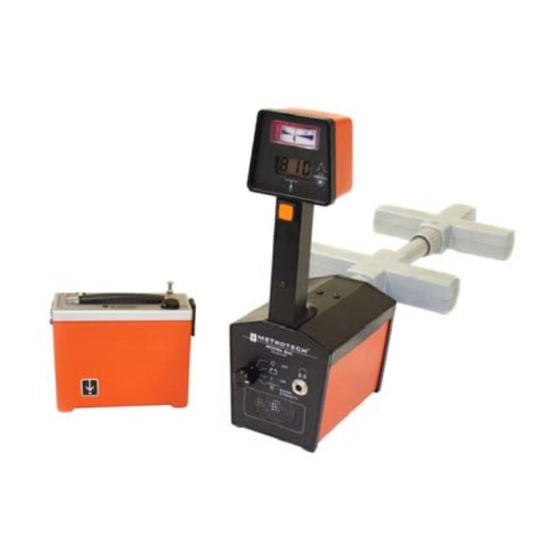
810™ Line Tracer
SERVICE CENTER, SALES AND TECHNICAL SUPPORT INFORMATION
Corporate Headquarters
3251 Olcott Street
Santa Clara, CA 95054
800-446-3392
408-734-1400 Direct
408-734-1415 Fax
www.metrotech.com
sales@metrotech.com
Warranty: One year. Specifications Subject to change without notice, ISO 9001:2000 Certified. Copyright 2008. All Rights Reserved
Metrotech Eastern U.S. Service Center
5211 Linbar Drive, Suite 503
Nashville, TN 37211
800-624-6210
615-366-7323 Direct
615-360-9855 Fax
nashville@metrotech.com
OPERATIONS MANUAL
Metrotech European Service Center
Seba KMT
Dr. Herbert Iann St. 6
96148 Baunach, Germany
+49 9 544 680
+49 9 544 2273 Fax
service@sebakmt.com
revision:11/06/08
Advertisement
Table of Contents

Related Manuals for Metrotech 810 Line Tracer


Summary of Contents for Metrotech 810 Line Tracer
- Page 1 810™ Line Tracer OPERATIONS MANUAL SERVICE CENTER, SALES AND TECHNICAL SUPPORT INFORMATION Corporate Headquarters Metrotech Eastern U.S. Service Center Metrotech European Service Center 3251 Olcott Street 5211 Linbar Drive, Suite 503 Seba KMT Santa Clara, CA 95054 Nashville, TN 37211 Dr.
- Page 2 ISO 9001 CERTIFIED Metrotech has received ISO 9001 Quality Management System Certification. Metrotech adheres to the quality standard guidelines of ISO 9001 and ensures quality in its design/development, production, installation, and servicing disciplines. © Metrotech Corporation 2008 Metrotech Corporation 3251 Olcott Street Santa Clara, CA 95054 Tel: 1.800.446.3392;...
-
Page 3: Table Of Contents
6.12 Locating a Service Lateral………………………………………25 6.13 Valves, Manhole Covers, Tees and Risers…………………….. 25 7. Maintenance…………………………………………………………………..26 7.1 810 Receiver Calibration………………………………………..26 7.2 Replacing the 810 Receiver Batteries…………………………..26 7.3 Replacing the 810 Transmitter Batteries……………………..…26 7.4 Metrotech Service Center……………………………………….27 8. Copyright………………………………………………………………….…..28 9. Warranty……………………………………………………………………. 28... - Page 4 List of Illustrations Figure Page 2-1 810 Line Tracer: Standard and Optional Equipment…………………..6 2-2 810 Transmitters: Controls and Indicators……………………………..9 2-3 810 Receiver: Controls and Indicators…………………………………10 3-1 Position of Receiver for Checkout Procedure, Step 6…………………11 3-2 Checkout of Receiver Directional Meter………………………………12 3-3 Configuration for Testing the Conductive Attachment………………..13...
-
Page 5: Introduction
1 INTRODUCTION The Metrotech Model 810 Radio Frequency Line Tracer is an excellent instrument for tracing water and gas distribution lines, cables, inductive locating, and blind searching. The high frequency signal is able to jump insulators and rubber gaskets often found in water and gas distribution systems. - Page 6 Figure 2-1: 810 Line Tracer: Standard and Optional Equipment...
-
Page 7: Standard Equipment
810 EQUIPMENT The Metrotech 810 Line Tracer consists of standard and optional equipment. All equipment is shown in Figure 2-1. 2.1 Standard Equipment Part Number Description Remarks Transmitter .25 watt 810 or Receiver 800C025 (metric) 800B004 Conductive Direct Connect Cable... -
Page 8: Technical Specifications
2.3 Technical Specifications 810 Transmitter Output Power: 250mW Output Frequency: 83.0775kHz ± .002% Crystal controlled for Interference resistance Battery Type: Six NEDA 13F “D” Cells, Alkaline Battery Life: 150 hrs. average Battery Check: Power on, push Power Test button Operation Temperature: 0 to 110°... -
Page 9: 810 Transmitter: Controls & Indicators
Figure 2-2: 810 Transmitter: Controls and Indicators 2.4 810 Transmitter: Controls and Indicators Figure 2-2 Designation POWER ON/OFF SWITCH Pull this switch to turn the Transmitter on. DIRECT/4820 CLAMP Output Jack Connection point for the Direct Connect cable Or any Metroclamp CONDUCTOR DIRECTION Arrow Orients the Transmitter when used in Inductive Mode. -
Page 10: 810 Receiver: Controls And Indicators
Figure 2-3: 810 Receiver: Controls and Indicators 2.5 810 Receiver: Controls and Indicators Figure2-3 Designation LEFT/RIGHT GUIDANCE METER The centerline needle guides you toward the conductor. If the needle id in the right-hand (solid) portion of the Meter, move the Receiver to the right. If the needle is in the left-hand (broken) portion of the meter, move the Receiver to the left. - Page 11 MODE SWITCH This switch has four possible settings: Power Off Battery Test In this position, needle should be to the right of the battery line. LineTracing Mode Use this position for normal operation. Field Strength Only This position eliminates the tone and Left/Right Guidance System and the depth measurement capability.
-
Page 12: Checkout Procedures
CHECKOUT PROCEDURE To insure proper operation of the 810 Line Tracer, use the checkout procedure below at he following times: • Upon receiving the equipment • Before each job, preferably before you leave for the site • If problems arise during a locate Checkout Steps: Turn the Transmitter ON/OFF switch to the “ON”... - Page 13 Figure 3-3: Configuration for Testing the Conductive Attachment To test the conductive attachment for loose or broken wires: Connect the BLACK and RED ends of the Conductive Attachment together. Lay the connected wires out on the floor in a circular configuration (see Figure3-3). Plug the Conductive Attachment into the DIRECT/4820 CLAMP jack of the Transmitter.
- Page 14 Turn both the Transmitter and Receiver off and unplug both the Metroclamp and the Conductive Attachment to avoid excessive battery loss. See Section 7 for information on testing and replacing batteries. If there are any questions about this procedure or the use of the instrument, contact the Metrotech Service Department: 1- 800-638-7682...
-
Page 15: Operation
Follow the checkout procedure described in Section 3 before operating the equipment. To operate the 810 Line Tracer, use the 810 Transmitter to apply a signal to the conductor, and use the 810 Receiver to trace the signal. DANGER – ELECTRICAL SHOCK When making a direct connection to a live power cable, always be sure the power to the cable is turned OFF by using a voltmeter to check for active electrical power. -
Page 16: Transmitter - Inductive Coupling With The Metroclamp
Pull the POWER SWITCH up to turn the Transmitter ON. Trace the signal with the Receiver; see Section 4.4 for Receiver Operating Instructions. 4.2 Transmitter – Inductive Coupling with a Metroclamp Use this method if Direct Connection is not possible, but you can position a Metroclamp around the conductor you want to trace. -
Page 17: Transmitter - Inductive Method
4.3 Transmitter – Inductive Method If you cannot make a direct Connection onto the conductor, or use the Metroclamp, use the internal antenna of the Transmitter to induce signal onto the conductor. See Figure 4-3. Figure 4-3: Signal Field Generated by Transmitter When in Inductive Use This is the least preferred method of inducing signal onto a conductor because the signal is broadcast through the soil and the air and can be picked up by other conductors in the area. - Page 18 Figure 4-5: Position of Receiver for Tracing Figure 4-6: 810 Receiver Guidance System...
-
Page 19: Using The Receiver
4.4 Using the Receiver The following describes using the Receiver with any of the three methods of applying Transmitter signal. Loosen the nut on the Receiver stem assembly and extend the stem as far as possible. Tighten the nut to secure the stem. Turn the Receiver MODE SWITCH to the third position. -
Page 20: Determining The Depth Of A Conductor
4.5 Determining the Depth of a Conductor To determine the depth of a conductor accurately, the 810 field strength must be greater than 500. Keep in mind that depth measurements are affected by soil condition, overhead lines, and adjacent conductors. In congested areas it is preferable to use Direct Connect when determining depth. -
Page 21: Conductor Identification Using A Second Metroclamp
Figure 4-8: Position of Metroclamps When Using Two Conductor Identification using a Second Metroclamp When exposed, multiple conductors are present, for example in conduits or ducts, use the method described below to identify a specific conductor. Plug a second Metroclamp cable into the jack marked AUX INPUT on the back of the Receiver. Set the Receiver MODE SWITCH to the fourth position –... -
Page 22: Ground Survey Procedure
Note: If you have any questions regarding marking requirements or procedures, please call your local One Call Center. GROUND SURVEY PROCEDURE Applications Regulations at construction sites often require a ground survey before any excavation is undertaken in the presence of underground utilities such as power, telephone, CATV, gas and water lines. Locating Conductors When undertaking a ground survey, use one of the three modes of operation (Direct Connect most accurate) to locate the known (if any) utilities and mark their location on the ground. -
Page 23: Tracing Techniques And Helpful Information
TRACING TECHNIQUES AND HELPFUL INFORMATION Many variables affect the process of locating a pipe or cable. The following information gives guidelines for various problem situations. 6.1 Soil Conditions Generally, the effect of soil types on line tracing is as follows: Soil Type Effect on Line Tracing moist, compact... -
Page 24: Completing The Circuit Path
When the Left/Right Guidance needle changes direction and the tone changes from broken to solid or solid to broken and the Left/Right Guidance meter needle moves in the same direction as you are moving. (Normally, the Left/Right Guidance needle moves in the opposite direction.) The field strength reading will drop as you move toward the “ghost”... -
Page 25: Locating A Service Lateral
Changing to a different Transmitter coupling point or coupling mode. Improving the grounding connection or moving the grounding point. Determine the location of the adjacent conductors. Then check to be sure that neither the direct connect cable or the ground cable cross over any of the adjacent conductors. -
Page 26: Maintenance
Receiver, for example, a buried service lone at your work location. If the Receiver gives significantly different centerline, signal strength, or depth information from what you know to be true, it should be re-calibrated by Metrotech or a Metrotech- authorized Service Center. -
Page 27: Metrotech Service Center
Internet: www.sebadyn.de Additional Metrotech Instruments: Multiple and Dual Frequency Locators, Fiber Optic Cable Locating System, Pipe and Cable Locators, Magnetic Locators, Sheath Fault Locators, Leak Detectors, Valve Box Locators, 50/60Hz Detectors, and a variety of transmitting sondes and flexi-sondes. -
Page 28: Copyright
Metrotech warrants its equipment to be free from defects in workmanship and material under normal and proper use and service for one year from date of purchase by original user. Metrotech assumes no obligation to repair or replace equipment which has been altered or repaired by other than a Metrotech-approved procedure, been subject to misuse, misapplication, improper maintenance, negligence, or accident;...
Need help?
Do you have a question about the 810 Line Tracer and is the answer not in the manual?
Questions and answers