Table of Contents
Advertisement
810 DX™ Pipe and Cable Locator
SERVICE CENTER, SALES AND TECHNICAL SUPPORT INFORMATION
Corporate Headquarters
3251 Olcott Street
Santa Clara, CA 95054
800-446-3392
408-734-1400 Direct
408-734-1415 Fax
www.metrotech.com
sales@metrotech.com
Warranty: One year. Specifications Subject to change without notice, ISO 9001:2000 Certified. Copyright 2008. All Rights Reserved.
Metrotech Eastern U.S. Service Center
5211 Linbar Drive, Suite 50
Nashville, TN 37211
800-624-6210
615-366-7323 Direct
615-360-9855 Fax
nashville@metrotech.com
OPERATIONS MANUAL
Metrotech European Service Center
Seba KMT
Dr. Herbert Iann St. 6
96148 Baunach, Germany
+49 9544 680
+49 9544 2273 Fax
service@sebakmt.com
Rev 9/9/08
Advertisement
Table of Contents

Related Manuals for Metrotech 810 DX


Summary of Contents for Metrotech 810 DX
- Page 1 810 DX™ Pipe and Cable Locator OPERATIONS MANUAL SERVICE CENTER, SALES AND TECHNICAL SUPPORT INFORMATION Corporate Headquarters Metrotech Eastern U.S. Service Center Metrotech European Service Center 3251 Olcott Street 5211 Linbar Drive, Suite 50 Seba KMT Santa Clara, CA 95054 Nashville, TN 37211 Dr.
- Page 2 ISO 9001:2000 CERTIFIED Metrotech has received ISO 9001:2001 Quality Management System Certification. Metrotech adheres to the quality standard guidelines of ISO 9001:2001 and ensures quality in its design/development, production, installation, and servicing disciplines. © Metrotech Corporation 2008 Metrotech Corporation 3251 Olcott Street, Santa Clara, CA 95054 Tel: 1.800.446.3392;...
-
Page 3: Table Of Contents
TABLE OF CONTENTS List of Illustrations………………………………………….4 1 Introduction ………………………………………………6 2 Safety Precautions………………………………………6 3 810DX Quick Start Guide for the Experienced User………………………………………..6 4 Model 810Dx Equipment………………………………..7 810Dx-D Standard Equipment…………………….7 810Dx-R Standard Equipment……………………..8 Accessories………………………………………….9 Technical Specifications…………………………..10 Transmitter: Controls Indicators, and Features …………………………..11 Receiver: Control, Indicators, and Features……………………………………………..14 5 Checkout Procedure…………………………………….17... -
Page 4: List Of Illustrations
Appendix………………………………………………………35 Copyright Notice……………………………………………..35 Warranty……………………………………………………….36 List of Illustrations Figure 4-1: Model 810Dx™ Pipe and Cable Locator - Standard Equipment…………………….……..7 Figure 4-2: Model 810Dx™ Pipe and Cable Locator with NiMH Transmitter Batteries……………….8 Figure 4-3: 810Dx Transmitter: Controls and Indicators……………………………………………….12 Figure 4-4: 810Dx Transmitter: Utility Line Resistance Chart……………………….…………….13 Figure 4-5: 810Dx Receiver: Controls and Indicators……………………………………………….14... - Page 5 Figure 7-2: Adjacent Utilities - Position of Ground Lead…………………………………………….. 27 Figure 7-3: Locating Service Laterals…………………. 28 Figure 7-4: Locating a Bend…………………………….. 28 Figure 7-5: Locating a Dead End……………………….. 28 Figure 7-6: Incorrect Coupling for Congested Area…………………………………………….. Figure 7-7: Correct Coupling for Congested Area……………………………………………..
-
Page 6: Introduction
This manual describes the Metrotech Model 810Dx™ Pipe and Cable Locator. Included is an equipment description, product specifications, checkout procedures, operating procedures, application information and maintenance instructions. The Model 810Dx is a state-of-the-art pipe and cable locator precisely designed with many powerful features to provide you with optimum information about your locate situation. -
Page 7: Model 810Dx Equipment
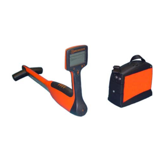
4.1 810Dx-D Standard Equipment (Alkaline Transmitter Batteries) Part # Description 10293 Receiver 83kHz 10294 Transmitter 83kHz 800B004 Conductive Attachment Direct Connect Assembly Ground Rod 10826 Hard Carrying Case 10943 Operation Manual Figure 4-1: Model 810Dx™ Pipe and Cable Locator - Standard Equipment 1. -
Page 8: Accessories
Part # Description 10293 Receiver 83kHz 10874 Transmitter 83kHz w/ NiMH Batteries 10793 Wall Mount Charger 800B004 Conductive Attachment Direct Connect Assembly Ground Rod 10826 Hard Carrying Case 10943 Operation Manual Notice: Please contact factory for wall mount chargers versions outside of USA and Canada. Figure 4-2: Model 810Dx™... -
Page 9: Technical Specifications
Part/Model # Description Remarks 4290 2” MetroClamp For Inductive Coupling 4490 4” MetroClamp For Inductive Coupling 4890 8” MetroClamp For Inductive Coupling 400B246 Conductive Attachment Telephone style Clips 400A132 100’ Ground Lead Extension 10873 12-volt DC power lead For use with external power source e.g. Vehicle cigarette lighter and transmitter battery recharging. - Page 10 TRANSMITTER Output Frequencies: 83.0775kHz Output indicator: Low/Medium/High LED Output Power: 1 Watt Power Settings: Low, Medium, High Modes: Direct connection, Clamp and Inductive Voltage protection: 250VAC Battery Type: Six D Cells Optional NiMH Battery Life: Alkaline 100 hours Continuous use NiMH 50 hours Continuous use, depending on power selection.
-
Page 11: Transmitter: Controls Indicators, And Features
Receiving frequency: 83.0775kHz Depth Accuracy: 0-10’ +/-(5% + 2”) under normal conditions 10’-20’ +/-(10% +2”) under normal conditions Features: Distance Sensitive Left/Right Guidance Real-Time Continuous Gain Adjustment Push Button Depth Backlighting standard Serial link RS232 Battery Type: Eight AA Alkaline Cells Battery Life: 85 hours continuous use 75 hours continuous backlit use... -
Page 12: Figure 4-3: 810Dx Transmitter: Controls And Indicators
810Dx TRANSMITTER 1 External Power/Charger Jack 2 Output Jack 3 Battery Door 4 ON/Off button 5 Power Level Output Button 6 Battery Charge State Indicator 7 Power level Indicator Figure 4-3: 810Dx Transmitter: Controls and Indicators Indicator LED Displays Three Types of Information 1) Battery Status –... -
Page 13: Figure 4-4: 810Dx Transmitter: Utility Line Resistance Chart
Please see Fig. 4-4 Standard Alkaline D cells or Rechargeable Batteries – Battery compartment can accommodate standard D cell alkaline batteries or Metrotech supplied NiMH battery pack. Smart charging circuit™ automatically detects presence of Alkaline or NiMH battery pack. -
Page 14: Figure 4-5: 810Dx Receiver: Controls And Indicators
810Dx RECEIVER Operating Frequency Battery Charge Status Distance Sensitive Left/Right Guidance Signal Strength Volume up/down arrows On/Off Depth Button Backlight Figure 4-5: 810Dx Receiver - Controls and Indicators 4.6 Receiver: Controls and Indicators 4.6.1 Receiver Controls and Indicators See Figure 4-5 for the location of the controls and indicators described below: ON/OFF Depth button - Turn ON by a quick press of the ON/OFF DEPTH button. -
Page 15: Figure 4-6: 810Dx Receiver Lcd Display
Receiver DISPLAY (Liquid Crystal Display) - Displays the battery status, operating frequency, Distance Sensitive Left/Right Guidance™, and signal strength. Battery Status Operating Frequency Distance Sensitive Left/Right Guidance Signal Strength Figure 4-6: 810Dx Receiver Display The receiver displays depth estimation in feet and inches or centimeters. Depth Button Figure 4-7: 810Dx Receiver LCD Display: Depth Mode 810DX 9/9/2008 REV D... - Page 16 SPEAKER - Emits audio tone to guide operator toward the targeted utility. BATTERY COMPARTMENT – To open, turn spring-loaded quarter-turn latch counter clockwise to release battery compartment door. Separate battery compartment from receiver housing, slide cover and gain access to the batteries. To open the battery compartment door, turn the spring- loaded quarter and separate the compartment door by gently pulling on the latch.
-
Page 17: Checkout Procedure
5 CHECKOUT PROCEDURE For proper operation of the Model 810Dx Pipe and Cable Locator, use this checkout procedure: • upon receiving the equipment • before each job, preferably before you leave for the site • if problems arise during a locate Place transmitter on the ground. -
Page 18: Operation
Figure 5-2: Aim Receiver at Transmitter 6 OPERATION Follow the Checkout Procedure described in Section 5 before operating the equipment. To operate the 810Dx Utility Line Locator use the Transmitter to apply the signal to the utility, and use the Receiver to trace the signal from the utility. WARNING Never make a direct connection to a live power cable. -
Page 19: Figure 6-1: Direct (Conductive) Connection
6.1.2 Methods of Applying Signal to a Utility - The three methods of applying the signal to the utility are - Direct Connect, Inductive Coupling, and Inductive. Following is a description of each method and instruction of use. A Direct (Conductive) Connection - This is the preferred mode of operation because the transmitter is connected directly to a metallic part of the utility (hydrant, meter, riser, valves, sheath, and tracer wire), allowing maximum signal to reach the utility. -
Page 20: Figure 6-2: Inductive Coupling With The Metroclamp
Transmitter Output Setting High 1.0 Watts Medium 0.5 Watts 0.2 Watts Decrease output power by pressing the OUTPUT button. Press once to decrease from HIGH to MEDIUM, MEDIUM LED now flashing. Press again to decrease from MEDIUM to LOW power. Press again to return to HIGH power. Transmitter Output Check –... -
Page 21: Receiver Operation
one utility. The signal is broadcast in all directions and can couple to every nearby utility through electromagnetic induction. It is possible to reduce the broadcasting signal by pressing the power output level button to change the power level from high to medium or medium to low. The transmitter induction antenna will be “ON”... -
Page 22: Figure 6-4: Receiver Position For Tracing
make sure the Receiver is not air coupled to the Transmitter. This can occur from 8 to 50 feet (2.5 to 15 m) from the Transmitter. To determine air coupling, find a centerline and lift the Receiver straight up. If the signal strength decreases smoothly, the receiver is not air coupled. -
Page 23: Figure 6-5: Receiver Position When Determining Depth
button for 3 seconds. Turn Receiver OFF by pressing the ON/OFF DEPTH button for 3 seconds. Disconnect the accessories when you have finished your locate. 6.2.2 Determining the Depth of a Utility - The depth of a utility may be determined in any of the Transmitter hook-up modes. -
Page 24: Figure 6-7: Receiver Position For Triangulation
Centerline and record the depth by pressing the ON/OFF depth button. Mark the centerline Tilt the Receiver away from the utility at a 45-degree angle – Touch the horizontal antenna to the ground while the tip of the receiver on the ground Move away from the utility - The Left/Right Guidance System will indicate another centerline. -
Page 25: Advanced Locating Techniques
conductive utility. Use triangulation to confirm the presence and depth of multiple utilities. Find the depth of the first utility and then continue to move away from the utility, marking each utility depth. Repeat the process to the other side and then calculate the depth of each utility. See figure 6-9. -
Page 26: Adjacent Utilities
move in parallel across and then down the survey area, parallel to one another. Operator 1 holds the Transmitter at his side and level with the ground. Operator 2 holds the Receiver vertically at his side with the top surface of the Receiver facing the Transmitter. -
Page 27: Deep Utility
Figure 7-2: Adjacent Utilities - Position of Ground Lead Move Ground Away From Pipe 7.3 Deep Utility - Signals picked up by the Receiver from deeply buried utilities are weaker and not as directionally distinct as those from pipes closer to the surface. In addition, the signal strength will only change by small increments in relation to moving the Receiver antenna. -
Page 28: Common Bonded Utilities
Figure 7-3: Locating Service Laterals Figure 7-4: Locating a Bend Figure 7-5: Locating a Dead End 7.8 Common Bonded Utilities - Telephone, power, and CATV sometimes use a common ground bond. If other utilities are connected to your target utility, putting a signal on the target can cause all the utilities to carry the same signal, making it difficult to identify the target utility. -
Page 29: Congested Areas
the utility and the Receiver. 7.10 Congested Areas - If you suspect that coupling from adjacent utilities is causing interference in the signal picked up by the Receiver, try increasing the strength of the signal on your utility and decreasing the strength of signal from the interfering utilities by: Changing to a different transmitter coupling point or coupling mode. -
Page 30: Determining If You Have A "Ghost" Utility
7.14 Non-Metallic Pipes - To trace nonmetallic pipe (sewer line) or duct, send the signal through the pipe by inserting the appropriate 83kHz Metrotech Sonde. For accurate depth readings with Sonde, refer to the sonde depth table to convert indicated depth to actual sonde depth. An alternative method is to insert a snake or fishtape into the pipe and connect the Direct Connect Cable from the Transmitter to one end of it. -
Page 31: Replacing The 810Dx D-Cell Transmitter Batteries
8.2 Replacing the 810Dx Alkaline D-Cell Transmitter Batteries with a NiMH battery pack See Figure 8-2. When replacing Alkaline D cells with Metrotech supplied NiMH rechargeable battery pack make sure to install battery with positive end first. See Figure 8-2. -
Page 32: Figure 8-4: Recharging The Nimh Battery Pack And Operating From An External 12-Volt Dc Supply
NiMH Transmitter battery. See Figure 8-2. Turn the Transmitter ”OFF”. Plug the Wall Mount cube into a 3-prong 120V socket. (Contact Metrotech for charger versions specific to the country where operating equipment). Insert the wall mount 2.5 mm plug into the EXTERNAL POWER/CHARGER JACK on the outside wall of the Transmitter. -
Page 33: Figure 8-5: Replacing The 810Dx Receiver Batteries
Figure 8-5: Replacing the 810Dx Receiver Batteries 8.3 Replacing the 810Dx Receiver Batteries - See Figure 8-4. Have ready eight AA batteries. Turn the spring-loaded quarter-turn latch on the underside of the 810Dx.Receiver body and remove the battery compartment. Carefully pull the battery compartment out of the unit. Slide the battery compartment cover to gain access to the batteries. -
Page 34: Service Center Information
For a Repair Service request form, go to www.metrotech.com/techsupport.asp. Download and print the Repair Service request form. Fill the requested information and place the form in the case. If you have any questions about your unit, please call the Metrotech's service center where the unit was sent. -
Page 35: Appendix
The information contained in this document is for informational purposes only and is subject to change without notice. Metrotech Corporation makes no warranty of any kind with regard to the information contained in this manual, including but not limited to the implied warranties of merchantability and fitness for a particular purpose. - Page 36 Metrotech. Warranty does not include batteries. Expendable items such as fuses and lamps are excluded.
Need help?
Do you have a question about the 810 DX and is the answer not in the manual?
Questions and answers