Table of Contents
Advertisement
Quick Links
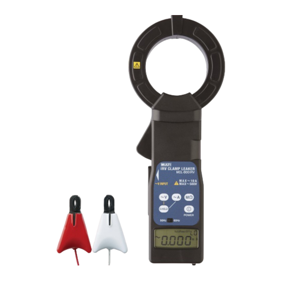
Io/Ior CLAMP LEAKER
MCL-800IR
INSTRUCTION MANUAL
Thank you very much for selecting our Io/Ior clamp leaker
model MCL-800IR.
This model is complex instrument and employ a very reliable
mechanical/electronic design.
Before you use your new instrument, read this instruction
manual completely and familiarize yourself thoroughly with
all functions and keep this instruction manual carefully to
take out whenever you need.
MULTI MEASURING INSTRUMENTS CO.,LTD.
Akihabara Murai Bldg., 7F, 1-26 Kanda Sakuma-cho,
Chiyoda-ku, Tokyo, 101-0025 Japan
TEL : 81-3-3251-7013 FAX : 81-3-3253-4278
Home Page :
http://www.multimic.com/
E-mail :
multi@multimic.com
Advertisement
Table of Contents

Related Manuals for MULTI MEASURING INSTRUMENTS MCL-800IR


Summary of Contents for MULTI MEASURING INSTRUMENTS MCL-800IR
- Page 1 MULTI MEASURING INSTRUMENTS CO.,LTD. Akihabara Murai Bldg., 7F, 1-26 Kanda Sakuma-cho, Chiyoda-ku, Tokyo, 101-0025 Japan TEL : 81-3-3251-7013 FAX : 81-3-3253-4278 Home Page : http://www.multimic.com/...
-
Page 2: Safety Summary
SAFETY SUMMARY observe by all means ● To use this instrument safely, read this “SAFETY SUMMARY” carefully and apply the instrument correctly. ● The CAUTIONs and WARNINGs which appear on the following pages are stated to prevent the operator & other people from the dangers and their properties from the damages beforehand. -
Page 3: Specifications
SPECIFICATIONS C URRENT DETECTION ZCT Inside diameter : Φ80mm Method : Split core type ZCT Withstanding voltage : AC 2000V/1 minute between CT core and grip M EASURING PART Measuring function : Leakage current (Io), Line current (I), Resistive leakage current (Ior), Voltage (V), Insulation Resistance (MΩ){calculated value} Measuring method : Clamp CT (in case of Ior, based on voltage standard) - Page 4 Operating temperature : 0~50℃, < 85%RH (without condensation) Storage temperature : -10~60℃, < 80%RH (without condensation) Auto power off : Approx. 10 minutes after power on Withstanding voltage : AC 2000V/1 minute between CT part and grip Consumption current : 14mA (approx. 48h for continuous use) Power supply : AAA alkali battery LR03×3 Dimension/Weight...
- Page 5 NAME OF EACH PART AND EXPLANATION ① ② ④ ⑤ ⑥ ⑩ ⑧ ③ ⑦ ⑪ ⑨ ⑫ ① Clamp Type ZCT : Sensor for detecting current and clamp method. ② Open/Close Lever : CT will open by pushing this lever to inside. ③...
- Page 6 ⑤ Current Range Switch (~A) : At the time of power switch on, the display is Io current value to be measured. By pressing this switch, the display becomes Ior value of single phase (1φ/Ior) and pressing once again, it becomes Ior value of 3 phase (Δ/Ior).
-
Page 7: Replacement Of Batteries
REPLACEMENT OF BATTERIES WARNING △ ! P OSSIBLE ELECTRICAL SHOCK OR ACCIDENT ● Do not replace the batteries under the conditions of clamping CT to the conductor and inputting voltage to the terminals. ● Do not operate the instrument with battery cover off. CAUTION △... - Page 8 MEASUREMENT For the safety operation keep and pay attention to the cautions and warnings stated in this manual. WARNING △ ! P OSSIBLE ELECTRICAL SHOCK ● This instrument is for the use of low voltage circuit. Do not make measurements of power lines carrying more than AC 600V. Before use, check and confirm the voltage of circuit to be measured.
- Page 9 N OTE: The power will become automatically off approx. 10 minutes after the switch operation due to auto power off function. Measurement of line current cannot be done on Ior current mode. Current measurement ranges of this instrument are auto but it can be changed to manual in case that the range cannot be fixed due to input fluctuation.
- Page 10 (4) Resistive Leakage Current (Ior) & Insulation Resistance (MΩ) Measurement ATTENTION FOR Ior/MΩMEASUREMSNET The insulation resistance measurement by this instrument is done on the live lines and the measured values may differ from ordinary insulation resistance testers in case. As the input voltage for measurement of insulation resistance in the circuit is different in case of single phase, 3 phase/3 wires and 3 phase/4 wires respectively, use the instrument correctly referring to the wiring methods.
- Page 11 1) Press once power switch ③ and Io current value is displayed. 2) Set the frequency range switch ⑦ to the circuit to be measured. 3) Input the voltage and current according to the circuit to be measured. As to details, refer to wiring method as under.
- Page 12 b. In case of Single Phase/Three Wires (Measuring Mode 1φ/Ior) LOAD White LOAD White c. In case of Three Phase/Three Wires (Measuring Mode Δ/Ior) White LOAD Black White Black...
- Page 13 d. In case of Three Phase/Three Wires (Neutral Grounding System) (Measuring Mode Y/Ior) LOAD White White Clamping CT to the grounding line is also available. (5) Change of Current Range The current range of this instrument becomes auto after power switch on. In case that the range cannot be fixed due to the large current fluctuation to be measured, however, the measurement cannot be done.
-
Page 14: Repair Service
5) To get 100mA range, press Current Range Switch once again and 100mA, 02 lightens. Keeping this condition, press Data Hold Switch again. 6) To get 1000mA range, press Current Range Switch further once and 1000mA, 03 lightens. Keeping this condition, press Data Hold Switch again. 7) To get 10A range, press Current Range Switch further once and 10A, 04 lightens.
Need help?
Do you have a question about the MCL-800IR and is the answer not in the manual?
Questions and answers