
Subscribe to Our Youtube Channel
Related Manuals for Mid-Continent Instruments 4300 Series


Summary of Contents for Mid-Continent Instruments 4300 Series
- Page 1 I NSTALLATI ON MANUAL AND OPERATI NG I NSTRUCTI ONS 4300-XXX Series Electric Attitude Indicator With Battery Backup MID-CONTINENT INST. CO., INC MANUAL NUMBER 9015762...
-
Page 2: Table Of Contents
Mid-Continent I nstruments, Wichita, KS Table of Contents Page Section 1 General Description Purpose of Equipment Physical Description Functional Description Gyro Warning Flag Options and Configurations Specifications Section 2 I nstallation General Pre-I nstallation I nspection Parts 2.3.1 I ncluded Parts 2.3.2 I nstaller Supplied Parts 2.3.3... - Page 3 Mid-Continent I nstruments, Wichita, KS Revision Detail Rev. Date Detail N/ R 10/ 1/ 03 Complete issue 11/ 4/ 03 Revise text for improved short battery test. Add text to Sec. 2.6.2.B for P/ N 36029 battery charger. 05/ 25/ 04 Update display configurations Fig.
-
Page 4: General Description
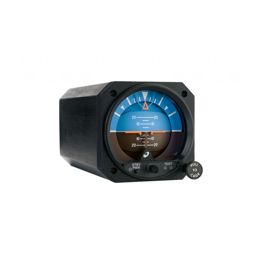
Mid-Continent I nstruments, Wichita, KS Section 1: General Description Purpose of Equipment The Model 4300-XXX Electric Attitude I ndicator with Battery Backup incorporates a moving display that simulates the earth’s horizon and provides the pilot with a real time visual indication of the aircraft pitch and roll attitude relative to the indicator symbolic airplane. -
Page 5: Gyro Warning Flag
Mid-Continent I nstruments, Wichita, KS without the specified battery intact. Battery substitution, modification, misuse and lack of specified maintenance will void all warranties and hold the manufacturer harmless from any and all claims or legal actions. Refer to an FAA authorized maintenance facility for testing and maintenance of this instrument excluding battery or light tray replacement. -
Page 6: Performance
Mid-Continent I nstruments, Wichita, KS Performance: Reliability 7500 Hour Mean Time Between Failure (MTBF). I nitial Erection: The "PULL TO CAGE" knob will erect the gyroscope to within 2.0° of case vertical in roll and pitch from any position at any time. Final Erection: The vertical gyroscope should be allowed to spin up for 3 minutes after rated power is applied and after initial erection. -
Page 7: Display Configurations
Mid-Continent I nstruments, Wichita, KS Face Layout A Face Layout B Rotating Roll Dial Fixed Roll Dial Fixed Pointer Rotating Pointer Traditional Symbolic Airplane Traditional Symbolic Airplane Standard Horizon Dial Standard Horizon Dial Face Layout C Face Layout D Rotating Roll Dial Fixed Roll Dial Fixed Pointer Rotating Pointer... - Page 8 Mid-Continent I nstruments, Wichita, KS Face Layout G Face Layout H Rotating Roll Dial Fixed Roll Dial Fixed Pointer Rotating Pointer Delta Symbolic Airplane Delta Symbolic Airplane High Resolution Horizon Dial High Resolution Horizon Dial Model I nput Roll Dial Horizon Dial Symbolic Face...
-
Page 9: Typical I Ndicator Display Detail
Mid-Continent I nstruments, Wichita, KS Roll Pointer: Fixed roll pointer: I ndicates aircraft roll displacement relative to a rotating roll dial. Rotating roll pointer: I ndicates aircraft roll displacement relative to a fixed roll dial. Gyro Warning Flag: I f loss of operating voltage should occur, gyro warning flag will come into view. -
Page 10: I Nstallation
Mid-Continent I nstruments, Wichita, KS Section 2: I nstallation General This section contains mounting, electrical connections and other information required for installation. After installation of cabling and before installation of the equipment, ensure that power is applied only to the pins specified in the interconnection diagram. CAUTI ON: GYROS ARE DELI CATE I NSTRUMENTS! THE FOLLOWI NG PRECAUTI ONS MUST BE OBSERVED!! A. -
Page 11: Parts
Mid-Continent I nstruments, Wichita, KS Parts 2.3.1 I ncluded Parts A. Model 4300-( ) Electric Attitude I ndicator including Battery Pack (P/ N 9015607). B. Mating Connector, MS3116F8-4S or equivalent (P/ N 9015514). C. I nstallation Manual (P/ N 9015762) 2.3.2 I nstaller Supplied Parts Mounting Screw, 6-32UNC-2A. -
Page 12: I Nstallation
Mid-Continent I nstruments, Wichita, KS I nstallation NOTE: Before installing unit, verify the option label on the unit matches the aircraft requirements for instrument voltage, lighting voltage/ color, and panel tilt. I nstall the Electric Attitude I ndicator within the aircraft in accordance with the aircraft manufacturer’s instructions and the following steps: A. -
Page 13: Continued Airworthiness
Mid-Continent I nstruments, Wichita, KS Continued Airw orthiness 2.6.1 BATTERY A. The battery is designed to be a user replaceable item if desired. Recommended replacement interval for the standby battery (P/ N 9015607) is 3 years because of diminished capacity (See Figures. 2.6 and 2.7 for more information). NOTE: The standby battery contains lead. - Page 14 ATTI TUDE I NDI CATOR No periodic scheduled maintenance or calibration is necessary for continued airworthiness of the 4300 series Electric Attitude I ndicator. I f the unit fails to perform to specifications, it must be removed and serviced by a qualified service facility.
-
Page 15: Outline Drawings
Mid-Continent I nstruments, Wichita, KS Figure 2.1 Outline Draw ing Rev J, September 1, 2009 Manual Number 9015762 Page 16 of 22... -
Page 16: Rear-Mount Cutout Dimensions
Mid-Continent I nstruments, Wichita, KS Figure 2.2: Panel Cutout Dimensions Figure 2.3: Front Mount Panel Cutout Dimensions Rev J, September 1, 2009 Manual Number 9015762 Page 17 of 22... -
Page 17: With 9015671 Kit
Mid-Continent I nstruments, Wichita, KS (When mounted Side View End View vertically) Figure 2.4: Remote Mount Standby Battery Option, using 9015671 Kit Contents of Standby Battery Remote Mount Kit: Part Number Description 7016975 Crimp Pin 7016983 Connector Housing Cap 7017676 Screw, 4-40x3/ 16 Pan Head Phillips 7018328 Contact Socket... -
Page 18: Operation
Mid-Continent I nstruments, Wichita, KS Section 3: Operation General This section describes the Model 4300-XXX Electric Attitude I ndicator operating procedures. The indicator is required to be installed in an aircraft with the specified inputs applied. Figure 1.2 provides an illustration of a typical Model 4300 display and a table describing indicator functions. Starting Procedures The following operational procedures are recommended when preparing the indicator for use: * * * * CAUTI ON* * * *... -
Page 19: Standby Battery Operation
Mid-Continent I nstruments, Wichita, KS B. Acceleration & Deceleration Errors Pitch/ roll indicating errors may occur due to accelerations experienced during takeoff, climb-out, descent, and landing. Errors that develop will be self-corrected by the internal erection system or manually corrected (in straight and level flight) by the actuation of the caging system. -
Page 20: Effect Of Low Temperature On Battery Capacity
Mid-Continent I nstruments, Wichita, KS C. Standby Battery Test The control panel on the front of the instrument incorporates a manual test feature. This test feature places the standby battery pack under load for approximately one minute (the gyro is used as a load) while displaying either a red or green light under the word TEST on the front panel. -
Page 21: Equipment Limitations
Mid-Continent I nstruments, Wichita, KS Equipment Limitations The Mid-Continent 9015607 battery pack is part of a complete system. When remote mounted, the 9015607 battery pack MUST be installed with the Mid-Continent 4300-XXX series Electric Attitude I ndicator with Battery Backup in order to be approved as a complete TSO’d system. This battery is not FAA approved if installed or used in any other w ay.
Need help?
Do you have a question about the 4300 Series and is the answer not in the manual?
Questions and answers