Table of Contents

Related Manuals for Mid-Continent Instruments 4300-4 Series


Summary of Contents for Mid-Continent Instruments 4300-4 Series
- Page 1 INSTALLATION MANUAL AND OPERATING INSTRUCTIONS 4300-4XX Series Electric Attitude Indicator MID-CONTINENT INST. CO., INC MANUAL NUMBER 9015762 9400 E 34 Street N, Wichita, KS 67226 USA REV B May 25, 2004 Phone 316-630-0101 • Fax 316-630-0723...
- Page 2 Mid-Continent Instruments, Wichita, KS FOREWORD This manual provides information intended for use by persons who, in accordance with current regulatory requirements, are qualified to install this equipment. If further information is required, please contact: Mid-Continent Instruments Attn: Customer Service Dept.
-
Page 3: Table Of Contents
Mid-Continent Instruments, Wichita, KS Table of Contents Page Section 1 General Description Purpose of Equipment Physical Description Functional Description Gyro Warning Flag Options and Configurations Specifications Section 2 Installation General Pre-Installation Inspection Parts 2.3.1 Included Parts 2.3.2 Installer Supplied Parts 2.3.3... - Page 4 Mid-Continent Instruments, Wichita, KS Revision Detail Rev. Date Detail 10/1/03 Complete issue 11/4/03 Revise text for improved short battery test. Add text to Sec. 2.6.2.B for P/N 36029 battery charger. 5/25/04 Update display configurations Fig. 1.1, update connector pinout: Lighting (No polarity), revise currents in table 1.3, add bezel dims to panel cutouts,...
-
Page 5: General Description
Mid-Continent Instruments, Wichita, KS Section 1: General Description Purpose of Equipment The Model 4300-4XX Electric Attitude Indicator incorporates a moving display that simulates the earth’s horizon and provides the pilot with a real time visual indication of the aircraft pitch and roll attitude relative to the indicator symbolic airplane. -
Page 6: Gyro Warning Flag
Mid-Continent Instruments, Wichita, KS without the specified battery intact. Battery substitution, modification, misuse and lack of specified maintenance will void all warranties and hold the manufacturer harmless from any and all claims or legal actions. Refer to an FAA authorized maintenance facility for testing and maintenance of this instrument excluding battery or light tray replacement. -
Page 7: Performance
Mid-Continent Instruments, Wichita, KS Performance: Reliability 7500 Hour Mean Time Between Failure (MTBF). Initial Erection: The "PULL TO CAGE" knob will erect the gyroscope to within 2.0° of case vertical in roll and pitch from any position at any time. -
Page 8: Display Configurations
Mid-Continent Instruments, Wichita, KS Face Layout A Face Layout B Rotating Roll Dial Fixed Roll Dial Fixed Pointer Rotating Pointer Traditional Symbolic Airplane Traditional Symbolic Airplane Standard Horizon Dial Standard Horizon Dial Face Layout C Face Layout D Rotating Roll Dial... - Page 9 Mid-Continent Instruments, Wichita, KS Face Layout G Face Layout H Rotating Roll Dial Fixed Roll Dial Fixed Pointer Rotating Pointer Delta Symbolic Airplane Delta Symbolic Airplane High Resolution Horizon Dial High Resolution Horizon Dial Model Input Roll Dial Horizon Dial...
-
Page 10: Typical Indicator Display Detail
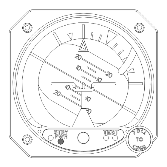
Mid-Continent Instruments, Wichita, KS Roll Pointer: A) Fixed roll pointer: Indicates aircraft roll displacement relative to a rotating roll dial. B) Rotating roll pointer: Indicates aircraft roll displacement relative to a fixed roll dial. Gyro Warning Flag: If loss of operating voltage should occur, gyro warning flag will come into view. -
Page 11: Installation
Mid-Continent Instruments, Wichita, KS Section 2: Installation General This section contains mounting, electrical connections and other information required for installation. After installation of cabling and before installation of the equipment, ensure that power is applied only to the pins specified in the interconnection diagram. -
Page 12: Parts
Mid-Continent Instruments, Wichita, KS Parts 2.3.1 Included Parts A. Model 4300-( ) Electric Attitude Indicator including Battery Pack (P/N 9015607). B. Mating Connector, MS3116F8-4S or equivalent (P/N 9015514). C. Installation Manual (P/N 9015762) 2.3.2 Installer Supplied Parts A. Mounting Screw, 6-32UNC-2A. Three (3) required. (1” long screws are suggested for panel thickness between 0.05 and 0.19, but may not be optimum in some installations. -
Page 13: Installation
Mid-Continent Instruments, Wichita, KS Installation NOTE: Before installing unit, verify the option label on the unit matches the aircraft requirements for instrument voltage, lighting voltage/color, and panel tilt. Install the Electric Attitude Indicator within the aircraft in accordance with the aircraft manufacturer’s instructions and the following steps:... -
Page 14: Continued Airworthiness
To restore a full charge, the battery should be periodically charged per Sect. 2.6.2, or removed from the installation and maintained on a charger such as is available from Mid-Continent Instruments. (P/N 36029) 5. No other periodic scheduled maintenance or calibration is necessary for continued airworthiness of the 4300 series Electric Attitude Indicator. -
Page 15: Outline Drawings
Mid-Continent Instruments, Wichita, KS Figure 2.1 Outline Drawing Rev B May 25, 2004 Manual Number 9015762 Page 15 of 21... -
Page 16: Rear-Mount Cutout Dimensions
Mid-Continent Instruments, Wichita, KS Figure 2.2: Panel Cutout Dimensions Figure 2.3: Front Mount Panel Cutout Dimensions Rev B May 25, 2004 Manual Number 9015762 Page 16 of 21... -
Page 17: With 9015671 Kit
Mid-Continent Instruments, Wichita, KS (When mounted Side View End View vertically) Figure 2.4: Remote Mount Standby Battery Option, using 9015671 Kit Rev B May 25, 2004 Manual Number 9015762 Page 17 of 21... -
Page 18: Operation
Mid-Continent Instruments, Wichita, KS Section 3: Operation General This section describes the Model 4300-4XX Electric Attitude Indicator operating procedures. The indicator is required to be installed in an aircraft with the specified inputs applied. Figure 1.2 provides an illustration of a typical Model 4300 display and a table describing indicator functions. -
Page 19: Standby Battery Operation
Mid-Continent Instruments, Wichita, KS B. Acceleration & Deceleration Errors Pitch/roll indicating errors may occur due to accelerations experienced during takeoff, climb-out, descent, and landing. Errors that develop will be self-corrected by the internal erection system or manually corrected (in straight and level flight) by the actuation of the caging system. -
Page 20: Nominal Battery Discharge Rate At 20°C
Mid-Continent Instruments, Wichita, KS C. Standby Battery Test The control panel on the front of the instrument incorporates a manual test feature. This test feature places the standby battery pack under load for approximately one minute (the gyro is used as a load) while displaying either a red or green light under the word TEST on the front panel. -
Page 21: Equipment Limitations
Mid-Continent Instruments, Wichita, KS EQUIPMENT LIMITATIONS The 4300-4XX series Electric Attitude Indicator is not to be used as a reference for aerobatic flight. It is recommended to turn off the Attitude Indicator (red flag showing) at least 5 minutes before aerobatic maneuvers are initiated.
Need help?
Do you have a question about the 4300-4 Series and is the answer not in the manual?
Questions and answers