
Related Manuals for ActronAir LC7-2W


Summary of Contents for ActronAir LC7-2W
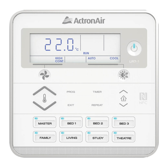
- Page 1 WALL CONTROL Installation Instructions Control Model Number LC7-2W LC7-2G IMPORTANT NOTE: Please read this manual carefully before installing or operating your air conditioning unit.
-
Page 2: Table Of Contents
• Storage conditions: -20 to 70 °C, < 90% RH non-condensing NOTE Do not use ActronAir 4 Core Data Cable Part Numbers: 4070-003 / AMDC4 or Non-Twisted Pair multi core cable. LC7-2 Control Interface Insert Document: 9590-3024 Ver. 2 200702... -
Page 3: 03. Installation
LC7-2 Control Interface Installation Guide 03. Installation 1. Remove back cover, as shown in the diagram below 2. Mount back cover to the wall • Insert and gently twist screwdriver into the slot at the top • Mount the back cover to the wall with screws (not and the bottom of the Control Interface. -
Page 4: 04. Wiring Diagram
LC7-2 Control Interface Installation Guide 04. Wiring Diagram 04.01. Single Wall Control to Indoor Board WALL CONTROL WIRING POWER: - BROWN / ORANGE 485 A: - BLUE 485 B: - BLUE-WHITE GND: - BROWN-WHITE / ORANGE-WHITE NOT USED: - GREEN / GREEN-WHITE WC-1 BR / OR BR / OR... -
Page 5: 05. Controller Assignment
LC7-2 Control Interface Installation Guide 05. Controller Assignment NOTE For installations where an LC7-2 is being installed with a Neo Wall Control, C-1 will always need to be assigned to the Neo Wall Control. Upon initial start up of the system, all connected LC7-2 controls (up to 3) will display C-0. After 3 seconds, an auto- assignment process will take place with the auto-assigned control ID displayed on the screen C-1, C-2 and C-3. -
Page 6: 07. Enabling Zones And Assigning Sensors
LC7-2 Control Interface Installation Guide 07. Enabling Zones and Assigning Sensors NOTE On initial power-up, an automatic zone detection takes place. If zones do not appear on the control upon commissioning, cycling power will enable another automatic zone detection. Press and hold the REPEAT and TIMER buttons for 3 seconds then release to enter Service Menu. Press the button to scroll through to Service Menu 14. -
Page 7: 09. Advance Series Self-Learn Mode (Evv Indoor Models)
LC7-2 Control Interface Installation Guide 4. Press the PROG button to accept changes. Display will show the zone CLOSE percentage and LOW. By default this will be 0. Press the buttons to change value. NOTE CLOSED and LOW range is 0-45%, with 5% increments per the buttons press. - Page 8 ©Copyright 2019 Actron Engineering Pty Limited ABN 34 002767240. ®Registered Trade Marks of Actron Engineering Pty Limited. ActronAir is constantly seeking ways to improve the design of it’s products, therefore specifications are subject to change without notice. Document: 9590-3024 Ver. 2 Issue Date: 07/2020...
Need help?
Do you have a question about the LC7-2W and is the answer not in the manual?
Questions and answers