Sungrow COM100D User Manual
Smart communication box
Hide thumbs
Also See for COM100D:
- User manual (42 pages) ,
- User manual (35 pages) ,
- User manual (43 pages)
Table of Contents
Advertisement
Quick Links
C C O O M M 1 1 0 0 0 0 D D / / C C O O M M 1 1 0 0 0 0 E E S S m m a a r r t t
C C o o m m m m u u n n i i c c a a t t i i o o n n B B o o x x U U s s e e r r
M M a a n n u u a a l l C C O O M M 1 1 0 0 0 0 D D _ _ E E - - U U E E N N - - V V e e r r 1 1 2 2 - -
2 2 0 0 2 2 1 1 0 0 7 7 V V e e r r s s i i o o n n : : 1 1 . . 2 2
COM100D_E-UEN-Ver12-202107 Version:1.2
COM100D/COM100E
S S m m a a r r t t C C o o m m m m u u n n i i c c a a t t i i o o n n B B o o x x
U U s s e e r r M M a a n n u u a a l l
Advertisement
Table of Contents

Related Manuals for Sungrow COM100D


Summary of Contents for Sungrow COM100D
- Page 1 COM100D_E-UEN-Ver12-202107 Version:1.2 COM100D/COM100E S S m m a a r r t t C C o o m m m m u u n n i i c c a a t t i i o o n n B B o o x x...
-
Page 3: Table Of Contents
C C o o n n t t e e n n t t s s 1 About This Manual ..................1 1.1 Validity ......................1 1.2 Type Description ..................1 1.3 Intended Use....................1 1.4 Target Group....................1 1.5 How to Use This Manual................2 1.6 Symbol Explanation.................. - Page 4 5.9 External DC Power Supply Cable ..............22 5.10 Inspection after Cable Connection............23 6 Commissioning ................... 24 6.1 Check before Commissioning..............24 6.2 Commissioning Steps................. 24 7 Grid Dispatching Function ..............26 7.1 Function Description .................. 26 7.2 Interface Description .................. 27 7.2.1 Digital Control Interface ..............
-
Page 5: About This Manual
MPLC primary node, and lighting device inside The magnetic base antenna and I/O module are optional components. If you want to purchase them, please contact SUNGROW. 1.3 Intended Use This manual is intended to provide the reader with detailed information on the COM 100 and describe how to install and operate the device. -
Page 6: How To Use This Manual
All rights reserved including the pictures, symbols, and markings used in this manual. Any reproduction or disclosure, even partially, of the contents of this manual is strictly prohibited without prior written authorization of SUNGROW. The content of the manual will be periodically updated or revised as per the product development. -
Page 7: Safety Instruction
B B e e f f o o r r e e I I n n s s t t a a l l l l a a t t i i o o n n After receiving the device, please check if there is damage caused during transport. Contact SUNGROW or the logistic company once any problem is detected. - Page 8 End user can never maintain or replace the modules and other parts. Serious personal injury or property loss may follow if otherwise. Never replace the internal components of the COM100 without authorization. SUNGROW shall not be held liable for any possible damage caused by ignorance of this warning.
-
Page 9: Product Introduction
Product Introduction 3.1 Function Description 3.1.1 Brief Introduction COM100 integrates the hardware and software functions of the data acquisition Logger1000 which applies to grid-connected scenarios below 540V, mainly including industrial, commercial, and household scenarios. It supports various networking modes and installation forms as well as the protection function. It features flexible networking, auxiliary maintenance, and easy operations. -
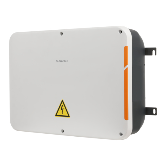
Page 10: Appearance
3 Product Introduction User Manual The equipment is a professional product. Non-professionals are strictly prohibited to install and operate this equipment. 3.2 Appearance D D e e s s c c r r i i p p t t i i o o n n I I t t e e m m N N a a m m e e Mounting ear... - Page 11 User Manual 3 Product Introduction F F i i g g u u r r e e 3 3 - - 1 1 COM100 dimensions W W i i d d t t h h ( ( W W ) ) H H e e i i g g h h t t ( ( H H ) ) D D e e p p t t h h ( ( D D ) ) 460mm...
-
Page 12: Mechanical Installation
Mechanical Installation 4.1 Unpacking and Inspection Check the scope of delivery for completeness according to the packing list. The following items should be included: F F i i g g u u r r e e 4 4 - - 1 1 Scope of delivery D D e e s s c c r r i i p p t t i i o o n n I I t t e e m m N N a a m m e e... -
Page 13: Location Requirements
User Manual 4 Mechanical Installation 4.2 Location Requirements With the ingress of protection IP66, the COM100 can be installed both indoors and • outdoors (more often). Operating temperature : -30℃ to +60℃; and ambient humidity: 5% to 95%, without • condensation. -
Page 14: Wall-Mounting
4 Mechanical Installation User Manual 4.4.1 Wall-Mounting Mount the COM100 onto the concrete wall or metal surface according to onsite conditions. Avoid drilling holes in the utility pipes and/or cables attached to back of the wall! Operation personnel should wear goggles and dust mask throughout the drilling process to avoid dust inhalation or contact with eyes. - Page 15 User Manual 4 Mechanical Installation Step 4 Use a rubber hammer to secure all the expansion bolts in the delivery accessories to the holes. Step 5 Use the nuts, flat washers, and spring washers in the delivery accessories to fix COM100 on the installation surface.
-
Page 16: Pole-Mounting (Optional)
- - - - E E n n d d 4.4.2 Pole-Mounting (Optional) COM100 can be mounted on a pole. If you need to purchase this scheme, contact SUNGROW who will provide the design drawings. Accessories supplied with the COM100 include matching screw assembly, nuts, brackets, clamps, etc. -
Page 17: Magnetic Base Antenna Connection (Optional)
User Manual 4 Mechanical Installation Step 2 Fix the mounting-brackets with the clamps by using the nuts. - - - - E E n n d d 4.5 Magnetic Base Antenna Connection (Optional) COM100 has a built-in antenna. If COM100 is installed in a container, a magnetic base antenna must be purchased to remove signal shielding. - Page 18 4 Mechanical Installation User Manual Step 3 Loosen the "RF" waterproof terminal on the bottom of the COM100. Step 4 Lead the antenna through the "RF" waterproof terminal, and secure clockwise the nut at the end of the antenna to the corresponding terminal on the bottom of the Logger1000. Step 5 Place the sucker antenna base on a metal surface outside the container.
-
Page 19: Electrical Connection
Electrical Connection 5.1 Waterproof Terminal Description F F i i g g u u r r e e 5 5 - - 1 1 Waterproof terminals on the bottom of COM100 Table 5-1 Description of waterproof terminals R R e e c c o o m m m m e e n n d d e e d d T T a a g g D D e e s s c c r r i i p p t t i i o o n n c c a a b b l l e e... -
Page 20: Internal Structure
5 Electrical Connection User Manual R R e e c c o o m m m m e e n n d d e e d d T T a a g g D D e e s s c c r r i i p p t t i i o o n n c c a a b b l l e e C C a a b b l l e e t t y y p p e e N N o o . -
Page 21: Grounding
User Manual 5 Electrical Connection Step 2 Turn off the COM100 power supply switch and MPLC switch. - - - - E E n n d d 5.4 Grounding Step 1 Strip the insulation cover of the grounding cable and crimp the stripped cable to the OT terminal. -
Page 22: External Ac Power Supply Cable
5 Electrical Connection User Manual 5.5 External AC Power Supply Cable COM100 is designed with an external AC power port at the bottom of the external 220 V AC power breaker, as shown in the figure below. Step 1 Loosen the two screws in the figure below and open the baffle. Step 2 Loosen the "AC (100~277V)"... -
Page 23: Rs485 Port
User Manual 5 Electrical Connection Step 5 Fasten the "AC (100~277V)" waterproof terminal. - - - - E E n n d d 5.6 RS485 Port For details about the wiring mode of the RS485 port, refer to the user manual of the data collector Logger1000. -
Page 24: I/O Module (Optional)
5.8 I/O Module (Optional) COM100 supports extension of the I/O module. If you want to purchase the I/O module, please contact SUNGROW. Step 1 Loosen the four screws on the I/O module baffle and open the baffle. Step 2 Use screws to fasten the PCB. - Page 25 User Manual 5 Electrical Connection Step 3 Use the dip switch to set the communication address to a value ranging from 1 to 15. B B i i n n a a r r y y a a d d d d r r e e s s s s D D e e c c i i m m a a l l a a d d d d r r e e s s s s C C o o m m m m u u n n i i c c a a t t i i o o n n a a d d d d r r e e s s s s s s e e t t u u p p...
-
Page 26: External Dc Power Supply Cable
5 Electrical Connection User Manual Step 6 Use a wire stripper to strip off the protective layer and insulation layer on the two sides of the communication cable, as shown in the figure below. Step 7 Connect one side of the cable to the "A2B2" port at the bottom of the data collector Logger1000, and the other side of the cable to the "AB"... -
Page 27: Inspection After Cable Connection
User Manual 5 Electrical Connection Step 3 Insert the stripped DC cable into the port "24V OUT +" and "24V OUT -" of the Logger1000. Step 4 Fasten the waterproof terminal. - - - - E E n n d d 5.10 Inspection after Cable Connection Conduct the following operations after finishing electrical cable connection: Check that all cables are correctly connected. -
Page 28: Commissioning
Commissioning 6.1 Check before Commissioning N N o o . . I I t t e e m m R R e e s s u u l l t t All cables are intact, well insulated, and appropriately □ dimensioned All cables are connected correctly and firmly □... - Page 29 Create new plant via the iSolarCloud App and check the □ iSolarCloud data for correctness. The auto search function is available for SUNGROW residential inverters and string inverters only whose addresses are automatically allocated. Devices of other types, such as Smart Energy Meter and transformer, can be connected to Logger1000 with the adding device function.
-
Page 30: Grid Dispatching Function
Multiple regulation manners can meet different regulation requirements. The COM100 can regulate the power output of the SUNGROW inverter, and the regulation mainly includes active power control and reactive power control. The COM100 can control device power output according to the local preset instructions. -
Page 31: Interface Description
User Manual 7 Grid Dispatching Function The corresponding power dispatching function is available only when the inverter supports active power control, power factor control, and reactive power regulation! For details, refer to the inverter user manual or consult the local retailers. 7.2 Interface Description The COM100 is equipped with digital control ports and analog control ports for receiving digital instructions and analog instructions sent from the grid dispatching center. - Page 32 7 Grid Dispatching Function User Manual In Germany and some other European countries, the grid company uses the Ripple Control Receiver to convert the grid dispatching signal and send it in a dry contact manner. In this case, the plant needs to receive the grid dispatching signal in the dry contact communication manner.
-
Page 33: Analog Control Interface
User Manual 7 Grid Dispatching Function F F i i g g u u r r e e 7 7 - - 3 3 Wiring of the active power dry contact 7.2.2 Analog Control Interface The analog control interface is at the bottom of the COM100, and a sum of 4 analog input ports are provided, as shown in the figure below. - Page 34 7 Grid Dispatching Function User Manual The DRM interface requires that the COM100 can be connected to the DRED via the corresponding wiring terminal or RJ45 connector.
-
Page 35: Web Interface
WEB Interface 8.1 Running Requirements I I t t e e m m P P a a r r a a m m e e t t e e r r System WIN7, WIN8, WIN10, or Mac OS Browser IE10 or later, Chrome45 or later, Safari11 or later Min. -
Page 36: Interface Introduction
After login for the first time, it is recommended to change the password. Click "O&M user" -> "Modify password" to change the password. In case the password is forgotten, contact SUNGROW to obtain a new one, with system time and Logger1000 S/N provided. - Page 37 User Manual 8 WEB Interface O O p p e e r r a a t t i i o o n n P P a a t t h h M M a a n n u u a a l l a a n n d d w w e e b b s s i i t t e e Quick guidance of the iSolarCloud App 1.
-
Page 38: Appendix
Appendix 9.1 Technical Parameters C C o o n n f f i i g g u u r r a a t t i i o o n n Support of management on a maximum of 30 Data collector devices Optional;... -
Page 39: Dry Contact Wiring Cable
The recommended maximum wiring distance is 10m. Use cat5e or higher specification network cable. Ethernet Communication distance should be less than 100m. 9.3 Quality Guarantee When product faults occur during the warranty period, SUNGROW will provide free service or replace the product with a new one. -
Page 40: Contact Information
E E x x c c l l u u s s i i o o n n o o f f L L i i a a b b i i l l i i t t y y In the following circumstances, SUNGROW has the right to refuse to honor the quality guarantee: The free warranty period for the whole machine/components has expired. - Page 41 C C h h i i n n a a ( ( H H Q Q ) ) A A u u s s t t r r a a l l i i a a Sungrow Australia Group Pty. Ltd. Sungrow Power Supply Co., Ltd...
- Page 42 User Manual R R o o m m a a n n i i a a T T u u r r k k e e y y Service Partner - Elerex Sungrow Deutschland GmbH Turkey +40 241762250 Istanbul service@sungrow-emea.com +90 216 663 61 80 service@sungrow-emea.com...
- Page 43 Sungrow Power Supply Co., Ltd. Add: No.1699 Xiyou Rd.,New & High Technology Industrial Development Zone, 230088,Hefei, P. R. China. Web: www.sungrowpower.com E-mail: info@sungrow.cn Tel: +86 551 6532 7834 / 6532 7845 Specifications are subject to changes without advance notice.
Need help?
Do you have a question about the COM100D and is the answer not in the manual?
Questions and answers