Table of Contents
Advertisement
Quick Links
Advertisement
Table of Contents

Related Manuals for Volth S-32


Summary of Contents for Volth S-32
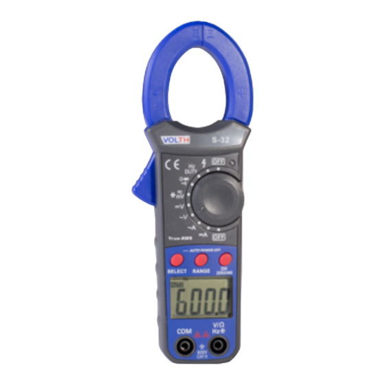
- Page 1 Mini True-RMS AC/DC Clamp Meter Mini True-RMS AC/DC Clamp Meter...
- Page 2 I. Introduction Welcome to use this product. VOLTH S-32 adopts high-performance MCU processor,it is Great Value as has high reliability,security, automatically setting range funcition,hand-held clamp meter etc.. the product has a large digital display, full range overload protection, data-hold function,...
- Page 3 3.1.5 Auto negative polarity indication: Displaying “-”. 3.1.6 Lack of battery power: Displaying “ ”. 3.1.7 Auto power OFF After turning on the instrument and without turning the function switch or pressing any button, the instrument will automatically enter into sleep mode after 10 minutes,to save battery power.when it is in the sleep mode you can press the SELECT key to wake up the instrument.
- Page 4 3.2.4 ACA Range Accuracy Resolution ± (4.5%+25d) 10mA 400A ± (4.5%+20d) 100mA 600A ± (2.5%+15d) AC Conversion Type:TRUE RMS responding, calibrated readings consistent with sinusoidal waveform RMS. Frequency Range:50~60Hz. 3.2.5 Resistance Ω Range Accuracy Resolution 400 Ω 0.1 Ω 4k Ω 1 Ω...
- Page 5 3.2.8 DUTY Range Accuracy Resolution 1%~99% ± (0.5%+3d) 0.1% Overload protection: effective value 250V . input sensitivity RMS:1V 3.2.9 Forward voltage drop of diode Displaying approximate forward voltage values of diode. Measuring condition: forward direct current is 1.5mA; opposite DC voltage is about 3 V. 3.2.10 Continuity Test In the case that the resistance between two tested points is less than about 90 ±20...
- Page 6 4.2 Measurement of AC/DC voltage 4.2 Measurement of AC/DC voltage Turn the Rotary switch to “V”. Then plug black lead in “COM” socket, and plug red lead Turn the Rotary switch to “V”. Then plug black lead in “COM” socket, and plug red lead in “V/Ω”...
- Page 7 (1) Turn the Rotary switch to the range of Ω / . At this time, the meter is reserved at resistance range. (2) Plug red lead in “V/Ω” socket, and plug black lead in “COM” socket (3) Connect the leads with the two ends of the circuit or component, and then read the value of resistance.
- Page 8 4.7 NON CONTACT VOLTAGE TESTING Set the rotary switch at the desired “ ” range position.NCV and ~symbol will be displayed on the LCD,connect the red test lead to “VΩ” jack and the black test lead without being connected, hold the red test lead to approach the phase line of commercial power, switch, or charge, (hold the red test lead to touch the metal ter minal if it is necessary), the meter will display “...
Need help?
Do you have a question about the S-32 and is the answer not in the manual?
Questions and answers