
Related Manuals for Lumen Dynamics Group OmniCure LX400+


Summary of Contents for Lumen Dynamics Group OmniCure LX400+
- Page 1 LX400+ UV LED Spot Curing System OmniCure® LX400+ UV LED Spot Curing System User Guide Lumen Dynamics 2260 Argentia Road Mississauga (ON) L5N 6H7 Canada +1 905.821.2600 www.LDGI.com 035-00413R Rev. 3...
- Page 2 Lumen Dynamics Group Inc. Every effort has been made to ensure information in this manual is accurate; however, information in this manual is subject to change without notice and does not represent a commitment on the part of the authors.
-
Page 3: Table Of Contents
LX400+ UV LED Spot Curing System Table of Contents: Introduction ................. 1 Safety ................... 2 Glossary of Symbols ..............2 Safety Precautions ..............4 Optical Safety Specifications............ 8 Getting Started..............13 System Components .............. 13 Front Panel ................14 Rear Panel ................15 Installation Procedures ............ - Page 4 LX400+ UV LED Spot Curing System PLC Connector ..............36 PLC Signal Descriptions ............37 Output Signals Requirements ..........41 Input Signals Requirements ........... 43 Remote Safety Interlock Connector ........43 Routine Care and Maintenance ........44 Cleaning Procedure for Head and Lens Assembly ....45 Lens Cleaning Procedure:............
- Page 5 LX400+ UV LED Spot Curing System Figures: Figure 1 Front Panel ..............14 Figure 2 Rear Panel Image ............15 Figure 3 Lens and Housing Subassembly ......19 Figure 4 Clamp ................. 19 Figure 5 Recommended Clamp Position ......20 Figure 6 Typical Installation Applications ......
-
Page 6: Introduction
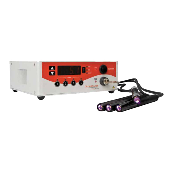
LX400+ UV LED Spot Curing System Introduction The LX400+ UV LED S represents a URING YSTEM new standard in UV LED Curing. It gives you the power, control, and reliability never before available in such a form factor. The OmniCure LX400+ joins the Lumen Dynamics family of light systems offering the same high level of innovation, quality and reliability that our customers have come to expect. -
Page 7: Safety
LX400+ UV LED Spot Curing System Safety Glossary of Symbols Caution risk of danger – consult accompanying documents Possible hazardous optical radiation/ UV emitted from this product. Use appropriate shielding. Input/Output Signals Input Signal Caution, Hot Surface DC (Direct Current) - 2 -... - Page 8 LX400+ UV LED Spot Curing System RISK GROUP 2 Caution Label: IEC 62471-2: 2009 (Located on top cover of LX controller chassis) Notice: UV radiation emitted from this product/ Hot Surface (Located on 365/ 385 nm LED head assemblies) Caution: Possibly hazardous optical radiation emitted from this product/ Hot Surface (Located on 400 nm LED head assembly) - 3 -...
-
Page 9: Safety Precautions
LX400+ UV LED Spot Curing System Safety Precautions This series of cautions and warnings relate to the installation, operation and maintenance of the OmniCure LX400+. They are also presented throughout this User‟s Guide as applicable. WARNING The protective eyewear provided is designed only for viewing of indirect UV light on an intermittent basis. - Page 10 LX400+ UV LED Spot Curing System RISK GROUP 2 CAUTION UV/ Hazardous visible radiation is emitted from this product. Eye or skin irriatation may result from exposure. Use appropriate shielding. WARNING When available LED Heads are installed, do not stare directly at the LED aperture(s).
- Page 11 LX400+ UV LED Spot Curing System Danger This system contains hazardous voltages, do not attempt to remove access covers. No user serviceable parts are located within the controller chassis or the UV LED head. It is recommended that ONLY QUALIFIED TECHNICAL PERSONNEL perform any testing or repairs.
- Page 12 LX400+ UV LED Spot Curing System with each LED head to provide user safety and optimum thermal management. Prior to handling of the UV LED head(s), allow a cool down for a period of approximately 5 minutes after system power has been removed. Caution –...
-
Page 13: Optical Safety Specifications
LX400+ UV LED Spot Curing System Optical Safety Specifications User Safety Data (IEC 62471: 2006) 2.3.1 Hazardous Distance Determinations (HD): Head Model 365nm Blue Light Hazard Radiance (determined from table 5.5 of IEC 62471) Distance Away From Head Distance Away From Head Along Plane of Beam Axis (mm) Normal to Beam Axis (mm) Head Model 365nm... - Page 14 LX400+ UV LED Spot Curing System Head Model 385nm Blue Light Hazard Radiance (determined from table 5.5 of IEC 62471) Distance Away From Head Distance Away From Head Along Plane of Beam Axis (mm) Normal to Beam Axis (mm) Head Model 385nm Weighted Skin Thermal Hazard Irradiance (determined from table 5.4 of IEC 62471) Distance Away From Head...
- Page 15 LX400+ UV LED Spot Curing System Head Model 400nm Blue Light Hazard Radiance (determined from table 5.5 of IEC 62471) Distance Away From Head Distance Away From Head Along Plane of Beam Axis (mm) Normal to Beam Axis (mm) Head Model 400nm Blue Light Hazard Radiance (determined from table 5.4 of IEC 62471) Distance Away From Head...
- Page 16 LX400+ UV LED Spot Curing System Test Results – Irradiance Summations (watt/m²) # = complied with Risk Group 1 ## = complied with Risk Group 2 Exempt Test Test Test Group Results: Results: Results: (IEC62471) Specified 365nm Head 385nm Head 400nm Head Max* Weighted...
- Page 17 LX400+ UV LED Spot Curing System Risk Group Test Results – Radiance Summations (watt/sr-m²) Irradiance Summations (watt/sr-m²) Risk Group: Risk Group: Risk Group: Specified (IEC62471) Maximum 365nm Head 385nm Head 400nm Head 1000 watt/sr-m² Blue Light Hazard Risk Group 1 Risk Group 1 Risk Group 1 Radiance...
-
Page 18: Getting Started
LX400+ UV LED Spot Curing System Getting Started System Components Carefully unpack the system and accessories. As you remove each item from the box place a check mark next to each item to ensure that all ordered components are present. Store the packaging and packing materials for future use. -
Page 19: Front Panel
LX400+ UV LED Spot Curing System Front Panel MODE SELECT BUTTON MODE INDICATORS DISPLAY WINDOW LED ON “ ” DOWN SELECT BUTTONS “ ” START STOP BUTTON FOR UV OUTPUT SYSTEM READY INDICATOR “ ” KEY SWITCH CHANNEL SELECT POWER ON 1/2/3/4 BUTTONS Figure 1 Front Panel... -
Page 20: Rear Panel
LX400+ UV LED Spot Curing System Rear Panel PLC CONNECTIONS OUTS 1 -12 TOP ROW 13-24 BOTTOM ROW LED HEAD INPUTS THROUGH VENTILATION SLOTS BOTH SIDES REMOTE SAFETY INTERLOCK CONNECTION 1 & 2 OUTS INPUT FOOT PEDAL INPUTS THROUGH Figure 2 Rear Panel Image - 15 -... -
Page 21: Installation Procedures
LX400+ UV LED Spot Curing System Installation Procedures General Installation Note: Before any installation occurs ensure the controller key is either removed from the unit or in the off position. Note: Prior to the following procedures it is determined that the user has established the LED UV head location and position based on the results of a series of testing and trials. -
Page 22: Led Head Cap Assembly/Removal Procedure
LX400+ UV LED Spot Curing System 4.1.6 Though the clamp can be located in any position on the head, for optimum heat dissipation resulting in optimum performance it is recommended that the clamp position on the head is as per Figure 5. -
Page 23: Clamp Installation And Removal
LX400+ UV LED Spot Curing System Clamp Installation and Removal 4.3.1 Ensure the clamp locking screw (M4 x 10, Allen Key Size 3mm) is loose before slipping the Clamp into the LED lens and head assembly. 4.3.2 Slide the clamp over the lens housing and onto the head and tighten the locking screw. -
Page 24: Figure 3 Lens And Housing Subassembly
LX400+ UV LED Spot Curing System LENS AND HOUSING SUBASSEMBLY PLACE PROTECTIVE LED HEAD CAP OVER THE LENS HOUSING Figure 3 Lens and Housing Subassembly M4 x 10 Allen Key Size 3mm Figure 4 Clamp Note: Refer to OmniCure® LED Head Assembly Specification Guide 035-00433R for LED Head specifications. -
Page 25: Figure 5 Recommended Clamp Position
LX400+ UV LED Spot Curing System PLACE PROTECTIVE LED HEAD CAP OVER THE LENS HOUSING THREADED LENS HOUSING LED APERTURE REFERENCE LINE FIRST CIRCULAR GROOVE RECOMMENDED CLAMP POSITION FOR BEST PERFORMANCE Figure 5 Recommended Clamp Position - 20 -... -
Page 26: Figure 6 Typical Installation Applications
LX400+ UV LED Spot Curing System Figure 6 Typical Installation Applications EXTENSION ROD FOR USE WITH STANDARD OPTICAL FIXTURES Figure 7 Extension Rod Application - 21 -... -
Page 27: Operation
LX400+ UV LED Spot Curing System Operation Note: Use UV Safety Eye Glasses provided before powering up the system. Powering Up/Powering Down 5.1.1 Ensure that the LED head(s) has been properly installed as per instructions in section 4. 5.1.2 Plug in the OmniCure LX400+ power adaptor into a properly grounded electrical outlet. - Page 28 LX400+ UV LED Spot Curing System 5.1.8 The controller will automatically go to Timer mode (green led indicator) on first sequential channel used and the controller‟s memory will display the previous timer setting (XXX.X, eg 10.0 for ten seconds, 0.0 if in count up mode).
-
Page 29: Mode Control
LX400+ UV LED Spot Curing System Mode Control 5.2.1 Upon completion of start-up cycle press MODE button to access timer, level and trigger control. Note: the controller will automatically go to the timer mode upon start up. 5.2.2 The MODE button is sequential, depressing the button will cycle through each control: 1. -
Page 30: Output Emission Level Control
LX400+ UV LED Spot Curing System Output Emission Level Control 5.4.1 Controls the emission output setting of each individual LED head. 5.4.2 Press and release the MODE button to access the out- put LEVEL control. The LEVEL LED will light up (color green). -
Page 31: Trigger Control
LX400+ UV LED Spot Curing System 5.5.2 When emission level % of selected channel(s) is disabled „OFF‟ (refer to section 5.4), during process countdown (using either the start/stop button or the Foot Pedal) the user is able to select that disabled channel from the front panel and the display will indicate selected channel „OFF‟... -
Page 32: Led Emission, Manual Control
LX400+ UV LED Spot Curing System Note: In either manual or automatic control the DISPLAY shows the channel selected only. To view other channels during LED emissions press the desired CHANNEL button. Note: To disable a channel either set channel emission level to OFF (reference section 5.4) or remove LED head from rear panel. - Page 33 LX400+ UV LED Spot Curing System 5.8.2 Press and release the DOWN or UP button so the display reads “cnt.d”. 5.8.3 Press and release the MODE button until the LEVEL LED on the front panel comes on (color green). Press the channel select button of the installed LED head.
-
Page 34: Head Hours-On Display
LX400+ UV LED Spot Curing System Head Hours-On Display Each head can be checked individually for “hours on” 5.9.1 time during non exposing time in any mode. 5.9.2 Hold the channel button for one second. The display automatically defaults to channel and displays the heads hours. -
Page 35: Led Display Mode S/C
LX400+ UV LED Spot Curing System 5.10 LED Display Mode S/C Note: To have the timer displayed during operation. This must be set prior to the start of the process; 5.10.1 Press and hold any channel button 5.10.2 Press mode button 5.10.3 Press up or down button to display (ref. -
Page 36: Table 1 Front Panel Button Functions Summary
LX400+ UV LED Spot Curing System Button Condition Description Press and release Timer control Temperature (Timer LED in Press and release temperature mode) Press and release Level Mode Press and release Trigger Press and release Temperature (Trigger LED) Press, hold, then FP- 1, FP- 2, FP- 3, FP- 4 release Press and release... -
Page 37: Table 2 Controller Led Indicators Summary
LX400+ UV LED Spot Curing System Controller LED Controller LED Description Indicator Status Mode to adjust the exposure time in Timer Green cnt.d (automatic) mode Mode to adjust the Level Green output power level. Mode to adjust the exposure timer Trigger Green operation (cnt.d) -
Page 38: Alarms
LX400+ UV LED Spot Curing System Alarms Alarm Situations 6.1.1 Over Temperature Protection. 6.1.2 LED light failure for LED head. 6.1.3 The LED UV Spot Curing System provides a flashing alarm (dim/bright) to alert the operator of various error conditions. The channel light will flash from on to off signifying an error alarm. -
Page 39: External Control
LX400+ UV LED Spot Curing System External Control Foot Pedal (FP) 7.1.1 Insert the foot pedal(s) 1 through 4 into connection ports on the rear panel of the controller (ref. Figure The system has the option of installing quantities 1 to 4 foot pedals. -
Page 40: Table 4 Foot Pedal Channel Control
LX400+ UV LED Spot Curing System FP1 Mode 1, 2 CONT FP2 Mode SIMULTAINIOUSLY 1, 2, 3 CONT SIMULTAINIOUSLY FP3 Mode CONTROLS ALL CHANNELS SIMULTAINIOUSLY FP4 Mode 1, 2 3, 4 CONT CONT FP5 Mode SIMULTAINIOUSLY SIMULTAINIOUSLY SEQUENTIALLY EXPOSES CH FP6 Mode COUNT DOWN MODE ONLY Table 4 Foot Pedal Channel Control... -
Page 41: Plc Connector
LX400+ UV LED Spot Curing System PLC Connector The rear panel of the main controller (ref. Figure has a PLC connection; it is a 24 pin terminal block connector, which has the following pin-outs; Table 5 PLC Connector Pin-Outs PIN # Description Location INTIN1... -
Page 42: Plc Signal Descriptions
LX400+ UV LED Spot Curing System PIN # Description Location SYNCOUT4(-) Pin 20 EMPTY Pin 20 STRT/STP3 Pin 22 STRT/STP4 Pin 23 TIMEIN Pin 24 PLC Signal Descriptions Pin 1 INTIN1 Analog input from 1.0VDC to 4.0VDC will set the output intensity of channel 1 from 15% to 100% in 1% increments. - Page 43 LX400+ UV LED Spot Curing System Pin 2 INTIN2 Analog input from 1.0VDC to 4.0VDC will set the output intensity of channel 2 from 15% to 100% in 1% increments. The following equation can be used to determine the output intensity based on a voltage input; y=(85x-40)/3 where;...
- Page 44 LX400+ UV LED Spot Curing System Pin 7 SYNCOUT3 (+) and Pin 19 SYNCOUT3(-) Signal output to indicate LED output of channel 3 status. When the LED head is on, the signal is active. When the LED head is off, the signal is inactive. Pin 8 SYNCOUT4 (+) and Pin 20 SYNCOUT4(-) Signal output to indicate LED output of channel 4 status.
- Page 45 LX400+ UV LED Spot Curing System Pin 13 INTIN3 Analog input from 1.0VDC to 4.0VDC will set the output intensity of channel 3 from 15% to 100% in 1% increments. The following equation can be used to determine the output intensity based on a voltage input; y=(85x-40)/3 where;...
-
Page 46: Output Signals Requirements
LX400+ UV LED Spot Curing System Pin 22 STRT/STP3 Shorting signal to GND will trigger channel 3. STRT/STP3 = 0V. Channel 3 triggers. STRT/STP3 = floating. No change. Pin 23 STRT/STP4 Shorting signal to GND will trigger channel 4. STRT/STP4 = 0V. Channel 4 triggers. STRT/STP4 = floating. -
Page 47: Figure 8 Active Low Signal Circuit Configuration
LX400+ UV LED Spot Curing System Figure 8 Active Low Signal Circuit Configuration Figure 9 Active High Signal Circuit Configuration - 42 -... -
Page 48: Input Signals Requirements
LX400+ UV LED Spot Curing System Input Signals Requirements 7.5.1 Characteristics of the „digital‟ input signal: Input device: optocoupler, photodiode, cathode side. Logic level: active low, zero voltage input. Maximum open circuit output voltage 6VDC. Maximum sinking current 5mA. ... -
Page 49: Routine Care And Maintenance
LX400+ UV LED Spot Curing System Routine Care and Maintenance Caution: Routine maintenance should only be completed by qualified personnel to avoid risk of injury to the end user. Warning: Use UV radiation eye and skin protection during servicing if access to the UV LED head is required during operation. -
Page 50: Cleaning Procedure For Head And Lens Assembly
LX400+ UV LED Spot Curing System 8.1.5 Ensure that cleaning solution does not come in contact with any electrical parts. Cleaning Procedure for Head and Lens Assembly 8.2.1 The lens assembly includes a coated lens and lens holder. Improper handling and cleaning practices can damage surfaces or coatings which are utilized in this assembly. -
Page 51: Lens Cleaning Procedure
LX400+ UV LED Spot Curing System 8.2.6 Cleaning Materials: The following materials are recommended for cleaning the Head Assembly. 1. Pressurized gas (filtered dry nitrogen). 2. Lint-free lens tissue, lint-free cotton swabs, lint or powder-free gloves or finger cots. 3. An organic solvent, such as reagent-grade isopropyl alcohol or lens cleaning solution. -
Page 52: Controller Cleaning Procedure
LX400+ UV LED Spot Curing System Controller Cleaning Procedure: 8.4.1 Ensure the controller is in the off position and the AC power cable is unplugged. 8.4.2 Use a mild soap solution as the cleaning media. 8.4.3 Dampen a clean lint free cloth, tissue or swab with the mild soap solution and wipe the exterior of the housing. -
Page 53: Troubleshooting
LX400+ UV LED Spot Curing System Troubleshooting 9.1.1 When a system error occurs the 4 digit, 7 segment display will flash. When head error occurs the LED indicator will flash. 9.1.2 The display will show system level error codes without the channel selection button having to be pressed. -
Page 54: Error Codes (Led Head)
LX400+ UV LED Spot Curing System Error Codes (LED Head) X= LED Input CH.1, CH.2, CH.3, CH.4. Er-1; The head(X) has exceeded the allowable operating temperature. (error code will remain present until cleared, however the head will be operative again when the temperature is below the maximum allowable). -
Page 55: Troubleshooting Symptom/Possible Cause
LX400+ UV LED Spot Curing System Troubleshooting Symptom/Possible Cause Service to be completed by qualified repair personnel only! If the controller fails to POWER up or function properly, use the following checklist to eliminate the most common causes of problems. Check for the following: 1. - Page 56 LX400+ UV LED Spot Curing System Error code Er-2 Check LED head to controller connections. Check level mode setting. Check timing mode settings. Check PLC connections. Error code Er-3 Check LED head to controller connections. ...
-
Page 57: Technical Specifications
LX400+ UV LED Spot Curing System Technical Specifications 10.1 Controller Specification LX400+ P/N 010-00243R Connectable Heads 1 to 4 individual LED heads. (365, 385 or 400nm) 4 front panel indicators: Timer control, Level, Mode Indication Trigger Mode and LED ON modes Mode and UP/Down button to control the display Mode Control mode. -
Page 58: Led Head Specification
LX400+ UV LED Spot Curing System 10.2 LED Head Specification Refer to OmniCure® LED Head Assembly Specification Guide 035-00433R for LED Head specifications. 10.3 Environmental Conditions Operating Conditions Ambient Temperature: 15ºC to 35ºC Altitude: 2000m max. Atmospheric Pressure: 700 to 1060 hPa ... -
Page 59: Regulatory Compliance
LX400+ UV LED Spot Curing System 10.4 Regulatory Compliance Product Safety: IEC 61010-1:2001 1990-Safety Requirements for Electrical Equipment for Measurement, Control and Laboratory Use Part 1. EN 61010-1:2001 Safety Requirements for Electrical Equipment for Measurement, Control and Laboratory Use. CAN/CSA C22.2 No. 61010-1-04 Safety Requirements for Electrical Equipment for Measurement, Control and Laboratory Use Part 1;... -
Page 60: China Rohs
LX400+ UV LED Spot Curing System 10.5 China RoHS The following table contains substance information for the OmniCure LX400+ System as required by China RoHS regulations: Names and Content of Toxic and Hazardous Substances or Elements Toxic and Hazardous Substances or Elements Parts Name Cr6+... -
Page 61: Weee Directive (2002/96/Eu)
LX400+ UV LED Spot Curing System 10.6 WEEE Directive (2002/96/EU) The symbol above indicates that this product should not be disposed of along with municipal waste, that the product should be collected separately, and that a separate collection system exists for all products that contain this symbol within member states of the European Union. -
Page 62: Fcc Part 15, Subpart B, Class A
LX400+ UV LED Spot Curing System 10.7 FCC PART 15, SUBPART B, CLASS A FCC Class A Digital Device or Peripheral – Information to User. NOTE This equipment has been tested and found to comply with the limits for a Class A digital device, pursuant to part 15 of the FCC Rules. -
Page 63: Warranty
LX400+ UV LED Spot Curing System Warranty Lumen Dynamics Group Inc warrants the original purchaser for a period of one (1) full year, calculated from the date of purchase, that the equipment sold is free from defects in material and workmanship. All repairs are warranted for 90 days. -
Page 64: Component Number Table
LX400+ UV LED Spot Curing System damages, in particular not for compensation of consequential damages. This warranty is not transferable. No warranty is extended to perishable items (if purchased separately or included in systems). These may include, but are not limited to, fuses, air filters, optical filters, cables, light guides, light lines, LED heads and light guide adapters. -
Page 65: Contact Information
LX400+ UV LED Spot Curing System Contact Information Lumen Dynamics 2260 Argentia Road Mississauga, Ontario L5N 6H7 CANADA Tel.:+1 905 821-2600 Toll.:+1 800 668-8752 (USA and Canada) Fax:+1 905 821-2055 omnicure@LDGI.com www.LDGI-omnicure.com Technical Assistance Techsupport.lsi@LDGI.com http://www.ldgi-omnicure.com/asc.php For a complete listing of Authorized OmniCure Distributors and Service Centers please go to the main web site: www.LDGI- omnicure.com...
Need help?
Do you have a question about the OmniCure LX400+ and is the answer not in the manual?
Questions and answers