
Related Manuals for Lumen Dynamics Group OmniCure 1500 Series


Summary of Contents for Lumen Dynamics Group OmniCure 1500 Series
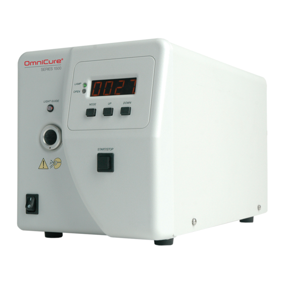
- Page 1 OmniCure Series 1500 ® UV Spot Curing System USER’S GUIDE Lumen Dynamics Group Inc. 2260 Argentia Road Mississauga (ON) L5N 6H7 Canada +1 905.821.2600 www.LDGI.com Printed in Canada 035-00364R Rev.3...
- Page 2 Lumen Dynamics Group Inc. Every effort has been made to insure information in this manual is accurate; however, information in this manual is subject to change without notice and does not represent a commitment on the part of the authors.
-
Page 3: Table Of Contents
User Guide Table of Contents Lumen Dynamics Group Inc..................I Introduction ......................1 Getting Started ....................... 2 Front Panel ....................... 2 Rear Panel ......................3 Safety Precautions ....................4 Installing the Lamp Module ................... 7 Inserting and Removing the Light Guide ............10 Powering Up and Powering Down .............. - Page 4 User Guide 19.1 Warning ....................... 42 19.2 China RoHS ....................43 19.3 WEEE Directive (2002/96/EU) ..............44 19.4 Mechanical Specifications ................44 19.5 Miscellaneous ....................44 Warranty ......................45 20.2 Replacement Bulb Warranty ................ 46 20.3 Returning your S1500 to Lumen Dynamics ..........46 Component Part Numbers ................
- Page 5 User Guide Table of Figures Figure 1 Front Panel......................2 Figure 2 Rear Panel ......................3 Figure 3 Lamp Housing Panel ..................7 Figure 4 Lamp Direction ....................8 Figure 5 Lamp Connection ....................8 Figure 6 Active Low Signal Circuit Configuration: ............16 Figure 7 Active High Signal Circuit Configuration: ............
-
Page 6: Introduction
Dynamics Group Inc (formerly EXFO Life Sciences & Industrial Division) has combined next generation optical engineering, state-of-the-art electronics and fiber-optics to produce sophisticated technologies that employ light. Today Lumen Dynamics Group Inc is a leading developer of light based systems for sectors ranging from manufacturing to bio-medicine and we are unmatched in our commitment to quality and service. -
Page 7: Getting Started
User Guide 2 Getting Started 2.1 Front Panel LAMP ON STATUS DISPLAY SHUTTER STATUS LIGHT GUIDE STATUS LIGHT GUIDE PORT MODE DOWN ADJUST BUTTONS POWER SWITCH START STOP BUTTON SHUTTER ACTIVATION Figure 1 Front Panel - 2 –... -
Page 8: Rear Panel
User Guide 2.2 Rear Panel PIN DE STYLE PORTS FOR PLC INTERFACING ADDITIONAL I/O (P2) STANDARD I/O (P1) ANALOG JACK FOOT PEDAL -232 PORT AC RECEPTACLE AND DUAL FUSE HOLDER Figure 2 Rear Panel - 3 –... -
Page 9: Safety Precautions
User Guide 3 Safety Precautions Glossary Caution risk of danger – consult accompanying documents Caution eye damage may result from directly viewing ultraviolet light – protective eye shielding and clothing must be used at all times. Input/Output Signals Input Signal The OmniCure S1500 is equipped with two safety sensors to protect the user from accidental UV exposure. - Page 10 The method in which lamps are disposed of must comply with local rules & regulations for disposal of hazardous materials. Lamps may be returned to Lumen Dynamics Group Inc., providing they are returned in its original packaging. Lumen Dynamics Group Inc.
- Page 11 User Guide Caution Prior to opening the unit and handling the lamp module, allow the lamp module to cool down completely (approximately 20 min). Caution Any electronic equipment connected to the OmniCure S1500 must be IEC950 certified. Cleaning Clean exterior of the unit with a water dampened cloth and simple detergent only. - 6 –...
-
Page 12: Installing The Lamp Module
User Guide 4 Installing the Lamp Module Note: Refer to Section 3 – Safety Precautions before proceeding 4.1.1 Be sure the AC POWER cord is disconnected from the unit. 4.1.2 Remove the screw from the lamp housing side panel using the tool provided (fastened to the bottom face) and remove the panel from the unit cover. -
Page 13: Figure 4 Lamp Direction
User Guide 4.1.4 As illustrated below position the lamp facing towards the front of the unit with the POWER leads facing towards you. The lamp should be aligned so that the leading edge of the reflector (lamp rim) fits into the mounting groove on the lamp holder assembly. - Page 14 User Guide 4.1.6 Locate the 4-pin Intelli-Lamp sensor connector at the rear of the lamp module and connect it to its mate located on the top of the lamp-housing wall. Tip: the Intelli-lamp connector will only attach in the correct orientation. If you are having difficulty attaching the connector, try rotating it by 180º.
-
Page 15: Inserting And Removing The Light Guide
5.1.4 To remove the light guide, firmly grip the strain relief near the light guide retainer and pull out firmly. Note: The OmniCure S1500 is designed for use with Lumen Dynamics Group Inc. Light Guides. Lumen Dynamics Group Inc. cannot guarantee the performance of the OmniCure S1500 if using light guides other than those supplied by Lumen Dynamics Group Inc. -
Page 16: Powering Up And Powering Down
User Guide 6 Powering Up and Powering Down Lamp Warm-UP: The ARC lamp has 3 distinct phases of operation; 1.Ignition. 2. Warm-up. Lumen Dynamics recommends 20 minutes of proper warm-up and to ensure a stable optical output. 3. Stable Operation. It is recommended that phase 1 and 2 are not interrupted. -
Page 17: Adjusting The Light Output
User Guide 7 Adjusting the Light Output Your OmniCure S1500 system includes an iris adjustment to control the intensity level of the light output from the unit. The intensity level adjustment is only possible through the DROP LED mode. 7.1 Adjusting the Light Output Warning: UV light will be emitted from the light guide. -
Page 18: Locking And Unlocking The Up/Down Adjustment Button
User Guide 8 Locking and Unlocking the UP/DOWN Adjustment Button 8.1.1 Your OmniCure S1500 system allows you to disable the up/down buttons. When the system is locked, no modifications to the set time or the optical output power can be made. This can help to ensure process control when multiple operators are using the same equipment. -
Page 19: Timed Exposures
User Guide 9 Timed Exposures Your OmniCure S1500 system includes a timer to automatically close the shutter after a user selected amount of time. Adjustments to the exposure time can only be made when the S1500 unit is in Timer Mode. 9.1 Adjusting the Exposure Time 9.1.1 The number shown will indicate the exposure time in seconds and tenth of seconds (XXX.X). -
Page 20: Input/ Output Signals And Descriptions
User Guide 10.1.2 The PLC I/O’s, foot pedal and RS-232 port are optically isolated from the control S1500 control electronics. This has been done in order to maximize the S1500’s immunity to noise and minimize its noise output. 10.2 Input/ Output Signals and Descriptions 10.2.1 Output Signals an output signal is said to be active when the output is ON •... -
Page 21: Figure 6 Active Low Signal Circuit Configuration
User Guide Figure 6 Active Low Signal Circuit Configuration: Figure 7 Active High Signal Circuit Configuration: - 16 –... -
Page 22: Figure 8 Rear Panel Sample Connection
User Guide 10.2.2 Input Signals The "digital" inputs have the following characteristics: >polarized type, input device optocoupler, photo-diode, cathode side >logic Level active low, zero voltage input >max open circuit output voltage: 6 VDC >max current sinking requirement: >logic low time for momentary 150mS, minimum The diagram below is a sample connection method which may be utilized for the S1500 rear panel I/O connections:... -
Page 23: Table 1 "P1" Pin-Out
User Guide 10.2.3 PLC Signal Descriptions The rear panel has an I/O signal connector labeled “P1”; it is a 15 pin DE style connector. It has the following pin-outs: PIN NO SIGNAL NAME Lamp ON out (-) Shutter verification out (-) Lamp ready out (-) Common for inputs (GND) Shutter activation (start/stop) in (+) - Page 24 User Guide 10.2.4 I/O signal connector (P1): signal descriptions Pins 1 (-) and 9 (+): Lamp on output This signal advises the user of the lamp status. When the lamp is ON the signal is active. When the lamp is OFF, the signal is inactive. Pins 2 (-) and 10 (+): Shutter verification output The shutter verification output signal remains inactive during successful shutter activations.
-
Page 25: Table 3 "P3" Pin-Out
User Guide Pins 4 (-) and 5 (+): Bulb alarm out This signal provides an indication of a lamp failure. The output signal, accessible through pins 4 and 5, is ON when an alarm condition is present. The optocoupler is OFF at all other times. -
Page 26: Audio Style Foot Pedal Connector: Signal Descriptions
User Guide 10.3 Audio Style Foot Pedal Connector: Signal Descriptions 10.3.1 The rear panel foot pedal connector, a 3 mm audio style jack, has the following pin-out: Connection Point SIGNAL NAME Outer Rim Positive input, active low Center Pin Common ground (GND) Table 4 Foot Pedal Pin-Out 10.3.2 This is a simple 2-wire, audio style jack that can be connected to a foot pedal (supplied with each unit) or any other electro-mechanical triggering device. -
Page 27: Messages / Indicators
User Guide 12 Messages / Indicators The OmniCure S1500 display provides information to the user to aid in unit operation and to advise when certain conditions exist. The following is a collective listing of messages and their meanings. 1. "XXXX." A flashing decimal point to the right of the four numbers on the display advises the user that the unit is in Lamp Hour Mode. - Page 28 User Guide 6. " end / bulb" The “end” and then “bulb” message appear in alternating sequence when POWER is first turned on to the unit if the accumulated lamp hours have reached 4000 hours. This indicates that the lamp has reached the end of safe life. If the lamp hours reach 4000 hours, safety measures will prevent the lamp from striking or extinguish the lamp if it is running.
-
Page 29: Led Indicators
User Guide 13 LED Indicators LED indicators display the status of the following: Light Guide • Lamp • Shutter • The following table describes LED status and descriptions of each status in details. LED Indicator Status Description Light Guide On – Green The light guide is fully inserted Light Guide On –... -
Page 30: Remote Automated Control Requirements
User Guide 15 Remote Automated Control Requirements 15.1.1 The S1500 system is designed to provide remote automated control of the UV spot curing system from a PC. 15.1.2 The S1500 PC software requirement specification below is used to describe the communication protocol between the S1500 unit and a PC. -
Page 31: Command Descriptions
User Guide 15.4 Command Descriptions: 1. Connect Series 1500 Command to S1500; CONN Response from S1500; READY 2. Disconnect SERIES 1500 Command to S1500; DCON Response from S1500; CLOSE 3. Lock the front panel Command to S1500; LOC Response from S1500; Received 4. - Page 32 User Guide 9. Close Shutter Command to S1500; CLS Response from S1500; Received 10. Turn On Lamp Command to S1500; TON Response from S1500; Received 11. Turn Off Lamp Command to S1500; TOF Response from S1500; Received 12. Get Lamp Configuration Command to S1500;...
- Page 33 User Guide 16. Get software versions from I/O board Command to S1500; VIO Response from S1500; n (n represents an integer number) Example: If “10XX\r” is responded, the software version on the I/O board will be 1.0. 17. Get SERIES 1500 serial number Command to S1500;...
-
Page 34: Command Timing Specification
User Guide 21. Set PLC Mode Command to S1500; SPMn Note: n, if n is 0 then trigger level mode is disabled. If n is 1 then trigger level mode is enabled. Response from S1500; Received – if the command has been accepted. Invalid –... - Page 35 User Guide ComPort->PutChar(Asc[Command_CRC>>4]); // send the CRC8 in hex string ComPort->PutChar(Asc[Command_CRC & (0xF)]); // send the CRC8 in hex string ComPort->PutChar('\r'); a=0; UnitResponse = ""; TimeOut = false; TimeOutTimer = 1; while (TimeOutTimer) Application->ProcessMessages(); if (a == '\r') a = 0; if (CompareCRC()) // Check if the data is received correctly...
- Page 36 User Guide CRC8 sample code: unsigned char CalcCRC8(unsigned char *Data) // calc 8 bit CRC unsigned char LoopCntr; unsigned char CRC8; unsigned char A; unsigned char i; CRC8 = 0; // reset CRC8 for (i = 0; i < 8; i++){ // data loop A = *Data++;...
-
Page 37: Routine Care And Maintenance
User Guide 16 Routine Care and Maintenance 1. Operate the unit in a well ventilated area with at least six inches clearance at the rear of the unit for proper air flow. Do not place any objects below the unit, between the feet as this will restrict airflow through the bottom of the front face plate. -
Page 38: Replacing The External Fuses
User Guide 16.2 Replacing the External Fuses 16.2.1 The external (mains) fuses are located in the fuse drawer which is located in the AC inlet module on the rear panel. 16.2.2 Turn off the main POWER switch and remove the AC POWER cord from the unit. 16.2.3 Gently pull out the drawer with the aid of a flat-head screwdriver. -
Page 39: Troubleshooting
User Guide 17 Troubleshooting Decimal Point Display Alarm Message Description Status Displays the accumulated hours the lamp has XXXX. Flashing L. Hrs Mode been on Displays the time in seconds the shutter will XXX.X Solid Timer Mode remain open when the start button is pressed Level Mode Displays the percentage the iris is open while in None... -
Page 40: Table 10 Front Panel Led Descriptions
User Guide LED Indicator Status Description ON – Green Light guide is fully inserted Light Guide ON – Red Light guide is not fully inserted The lamp is ON Lamp The lamp is OFF The shutter is open Open The shutter is closed Table 10 Front Panel LED Descriptions Front Panel Buttons Position... - Page 41 User Guide 17.1.3 If the shutter does not open, check that: 1. The light guide is fully inserted; the LED above the light guide port will be illuminated green. The lamp is warmed-up; the display is not flashing. The shutter interlock input is not active (P1, pins 6 &...
-
Page 42: Technical Specifications
User Guide 18 Technical Specifications 18.1 Lamp Module A – Rim of Lamp Reflector B – Reflector C – Back ceramic Mount D – Intelli-Lamp Connector E – Power Connector Lamp Module Lumen Dynamics Enhanced 200watt UV lamp 52.8 mm Focal Point of Spot 2000 hours Lamp Module Life... -
Page 43: Light Guide
User Guide 18.2 Light Guide Light Delivery Flexible High Power Fiber Light Guides will be available in a variety of lengths with a variety of core diameters. Note: 3mm single leg liquid light guides are not compatible with the S1500! 18.3 Power Input Power Supply: Power Factor Corrected, Universal Input... -
Page 44: I/O Ports (Including Rs-232)
User Guide 18.4 I/O Ports (including RS-232) 18.4.1 The S1500 has 4 different I/O ports; 4 located on the back of the unit. The 1st port is a simple 2-wire, audio style jack that can be connected to a foot pedal (supplied with each unit) or any other electro-mechanical triggering device. -
Page 45: Noise And The Omnicure S1500
User Guide 18.7 Noise and the OmniCure S1500 Using the S1500 in a Noisy Environment 18.7.1 What is Noise? "Electrical noise" is a term used to describe unwanted electronic emissions. Noise is actually comprised of RFI (Radio Frequency Interference) EMI (Electro Magnetic Interference) and other similar sources of energy. -
Page 46: Regulatory Compliance
User Guide Depending on the noise Level in the environment, any combination or all of the above shielding recommendations may be necessary to protect the S1500 from noise and ensure smooth operation. We can help you to shield the S1500 from electrical noise. -
Page 47: Warning
User Guide FCC Class B Digital Device or Peripheral - Information to User NOTE This equipment has been tested and found to comply with the limits for a Class B digital device, pursuant to part 15 of the FCC Rules. These limits are designed to provide reasonable protection against harmful interference when the equipment is operated in residential installation. -
Page 48: China Rohs
User Guide 19.2 China RoHS 19.2.1 The following table contains substance information for the Omnicure S1500 as required by China RoHS regulations. 有 毒 有 害 物 质 名 称 及 含 量 的 标 识 格 式 有 毒 有 害 物 质 或 元 素 部... -
Page 49: Weee Directive (2002/96/Eu)
User Guide 19.3 WEEE Directive (2002/96/EU) 19.3.1 The symbol above indicates that this product should not be disposed of along with municipal waste, that the product should be collected separately, and that a separate collection system exists for all products that contain this symbol within member states of the European Union. -
Page 50: Warranty
User Guide 20 Warranty 20.1.1 Lumen Dynamics Group Inc. warrants the original purchaser for a period of one (1) full year, calculated from the date of purchase, that the equipment sold is free from defects in material and workmanship. All repairs are warranted for 90 days. -
Page 51: Replacement Bulb Warranty
User Guide 20.2 Replacement Bulb Warranty 20.2.1 If the OmniCure 200 watt bulb fails to strike during the warranty period of 2000 hours, the bulb will be replaced under warranty. In the event of a claim under this guarantee, the lamp is to be sent postage and carriage paid, including a description of the fault, to the Lumen Dynamics Service Centre. -
Page 52: Component Part Numbers
User Guide 21 Component Part Numbers Product Part Number The OmniCure S1500 UV Spot Curing Unit P010-00224R S1500 with Standard Filter (320nm-500nm) The OmniCure S1500 UV Spot Curing Unit P010-00225R S1500 with Optional Filter (specified at Order) The Enhanced 200W lamp module 012-64000R UV Safety Glasses 854-00001R... -
Page 53: Contact Information
User Guide 22 Contact Information Lumen Dynamics 2260 Argentia Road Mississauga, Ontario L5N 6H7 CANADA Tel.:+1 905 821-2600 Toll.:+1 800 668-8752 (USA and Canada) Fax:+1 905 821-2055 omnicure@ldgi.com www.ldgi-omnicure.com Technical Assistance Techsupport.lsi@ldgi.com For a complete listing of Authorized OmniCure Distributors and Service Centers please go to the main web site: www.ldgi-omnicure.com - 48 –...
Need help?
Do you have a question about the OmniCure 1500 Series and is the answer not in the manual?
Questions and answers