
Related Manuals for Mitsubishi Heavy Industries SRK20HD


Summary of Contents for Mitsubishi Heavy Industries SRK20HD
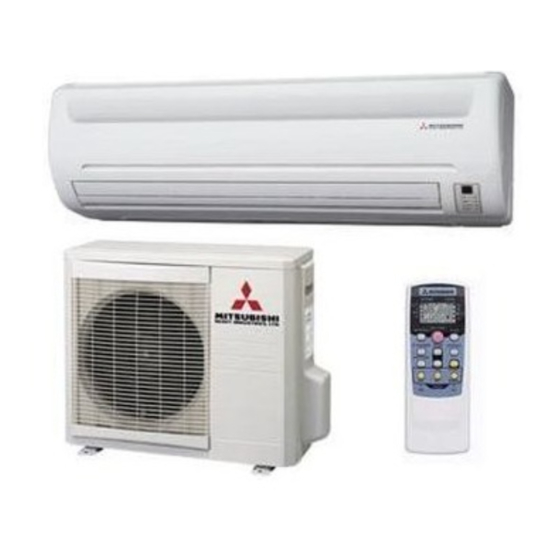
- Page 1 Manual No. ’05 . SRK-T . 045 Collection data WALL MOUNTED TYPE ROOM AIR-CONDITIONER (Split system, air to air heat pump type) SRK20HD http://splitoff.ru/tehn-doc.html...
-
Page 2: Table Of Contents
CONTENTS 1. GENERAL INFORMATION ................1 Specific features ..................1 How to read the model name ..............1 2. SELECTION DATA................... 2 Specifications ................... 2 Range of usage & limitations ..............3 Exterior dimensions ................. 3 Piping system ................... 4 Selection chart .................. -
Page 3: General Information
GENERAL INFORMATION 1.1 Specific features The “Mitsubishi Daiya” room air-conditioner: SRK series are of split and wall mounted type and the unit consists of indoor unit and outdoor unit with refrigerant precharged in factory. The indoor unit is composed of room air cooling or heating equipment with opera- tion control switch and the outdoor unit is composed of condensing unit with compressor. -
Page 4: Selection Data
SELECTION DATA 2.1 Specifications Model SRK20HD (Indoor unit) SRC20HD (Outdoor unit) (220/230/240V) Model SRK20HD SRC20HD Item Cooling capacity 2000 Heating capacity 2200 Power source 1 Phase, 220-240V, 50Hz Cooling input 0.635 Running current (Cooling) 3.1/3.0/2.9 Heating input 0.605 Running current (Heating) 3.0/2.9/2.8... -
Page 5: Range Of Usage & Limitations
Voltage at starting Min. 85% of rating Frequency of ON-OFF cycle Max. 10 times/h ON and OFF interval Max. 3 minutes 2.3 Exterior dimensions (1) Indoor unit Model SRK20HD Unit: mm Piping hole right(left) Terminal block 117.5 117.5 216.5 216.5 216.5... -
Page 6: Piping System
Terminal block 61.9 Service valve (Liquid) 139.3 33.3 Flare connecting ø6.35 (1/4") Service valve (Gas) Flare connecting ø9.52 (3/8") 2.4 Piping system Model SRK20HD Indoor unit Outdoor unit Cooling cycle Heating cycle Outdoor air Flare connecting Service valve temp. sensor (Gas) -
Page 7: Selection Chart
0.92 1.00 How to obtain the cooling and heating capacity Example : The net cooling capacity of the model SRK20HD with the piping length of 15m, indoor wet-bulb temperature at 19.0˚C ✕ ✕ and outdoor dry-bulb temperature 35˚C is Net cooling capacity = 2000 0.975... -
Page 8: Electrical Data
ELECTRICAL DATA 3.1 Electrical wiring Model SRK20HD : http://splitoff.ru/tehn-doc.html... -
Page 9: Outline Of Operation Control By Microcomputer
OUTLINE OF OPERATION CONTROL BY MICROCOMPUTER 4.1 Operation control function by remote control switch Remote controller Model SRK20HD S Operation section FAN SPEED button OPERATION MODE select button Each time the button is pushed, the indi- Each time the button is pushed, the indi- cator is switched over in turn. -
Page 10: Unit On/Off Button
Unit indication section Model SRK20HD RUN (HOT KEEP) light (green) • Illuminates during operation. • Flashes at air flow stop due to the ‘HOT KEEP’. TIMER light (yellow) Illuminates during TIMER operation. HI POWER light (green) Illuminates during HI POWER operation. -
Page 11: Flap Control
4.4 Flap control Control the flap by AIRFLOW button on the wireless remote controller. (1) Air scroll The flap will be automatically set to the angle of air flow best to operation. (a) Starting time of operation During cooling and During heating dry operation operation... -
Page 12: Outline Of Heating Operation
4.6 Outline of heating operation (1) Operation of major functional components Item When the compressor When the compressor When the compressor goes Functional command is OFF command is ON OFF due to an abnormal stop. components Indoor fan motor Flaps ON or OFF ON or OFF Stop position control... - Page 13 (b) When the compressor and outdoor fan are stopped 1) While the compressor operation is delayed. 2) Up until 5 minutes have passed Speed 6 since the end of a compressor Auto fan control, Speed 4 or the set fan speed start delay operation, when 52C Speed 2 Speed 2...
- Page 14 (c) Operation of functinal components during defrosting operation Compressor command Hot keep Controlled by the indoor heat Hot keep exchanger temperature Indoor unit fan The chart at left is for reference. Hot keep control governs operation Operating lamp during heating. Flashes Outdoor unit fan 110 sec.
-
Page 15: Outline Of Cooling Operation
4.7 Outline of cooling operation (1) Operation of major functional components Item When the compressor When the compressor When the compressor goes Functional command is OFF command is ON OFF due to an abnormal stop. components Indoor fan motor Flaps ON or OFF ON or OFF Stop position control... -
Page 16: Outline Of Dehumidifying Operation
4.8 Outline of dehumidifying operation (1) Choose the appropriate operation block area by the difference between room temperature and thermostat setting temperature as shown below. ¡ Operation block area D Block C Block B Block A Block –2 Room temp. – Setting temp.(deg) (2) Start up operation C.D Block A.B Block... -
Page 17: Automatic Operation
4.9 Automatic operation (1) Determination of operation mode The blow operation of the indoor fan is carried out at the 1st speed for 20 seconds and the room temperature is checked to determine the operation mode automatically. (When the unit is operated by the turn-on timer, the blow operation is not carried out.) <... - Page 18 (5) High-pressure control The indoor heat exchanger sensor detection temperature controls the outdoor fan and compressor. ¡ When the indoor heat exchanger ¡ When the indoor heat exchanger temperature is > = 58˚C temperature is > = 62˚C Outdoor fan Compressor Indoor heat exchanger temp.
-
Page 19: Application Data
APPLICATION DATA SAFETY PRECAUTIONS ¡ Please read these “Safety Precautions” first then accurately execute the installation work. ¡ Though the precautionary points indicated herein are divided under two headings, WARNING and CAUTION , those points which are related to the strong possibility of an installation done in error resulting in death or serious injury are listed in the WARNING section. -
Page 20: Selection Of Location For Installation
(ii) Design the base higher than possible snow deposit. snow deposit height (3) Limitations for one way piping length and vertical height difference. Model SRK20HD Item One way piping length (R) 15 m Outdoor Vertical height unit is lower... -
Page 21: Installation Of Indoor Unit
5.2 Installation of indoor unit (1) Installation of installation board (a) Fixing of installation board Look for the inside wall structures (Intersediate support or INSTALLATION SPACE (INDOOR UNIT) (FRONT VIEW) pillar and firaly install the unit after level surface has been Unit : mm checked.) Speace for... - Page 22 (3) Preparation of indoor unit (a) Mounting of connecting wires 1) Remove the lid (R). 2) Remove the terminal cover. 3) Remove the wiring clamp. 4) Connect the connecting wire securely to the terminal block. Terminal block Use cables for interconnection wiring to avoid loosening of the wires.
-
Page 23: Installation Of Outdoor Unit
(4) Installation of indoor unit (a) Install the indoor unit on the mounting plate. Hook the upper part of the indoor unit on the stoppers disposed at the upper part of the mounting plate and lightly push the lower part of the indoor unit so that the unit is fixed in position. ¡... - Page 24 (2) Connection of refrigerant piping Indoor unit side Outdoor unit side ¡ Connect firmly gas and liquid side pipings ¡ Connect firmly gas and liquid side by Torque wrench. pipings by Torque wrench. Spanner (for fixing the piping) Torque wrench ¡...
-
Page 25: Test Run
It is very important to be careful of above when pulgging in the unit to an already furnished electrical outlet. (4) Explain to the customer on the correct usage of the air conditioner in simple layman’s terms. (5) Make sure that drain flows properly. (6) Standard operation data (220/230/240V) Model SRK20HD Item Cooling High pressure MPa(kgf/cm Heating 1.48~1.64 (15~17) Cooling 0.57~0.69 (6~7) -
Page 26: Maintenance Data
MAINTENANCE DATA 6.1 Trouble shooting (1) Trouble shooting to be performed prior to exchanging PCB, (Printed circuit board) [Common to all models] All the models described in this chapter are controlled by a microcomputer. When providing maintenance service to customers it is necessary to understand the function controlled by a micro computer thoroughly, so as not to mistakenly identify correct operations as mis-operations. - Page 27 (2) Self diagnosis display on indoor unit RUN light Outdoor unit LED Trouble Cause ¡ Broken heat exchanger sensor wire, connector Heat exchanger sensor error 1 time flash poor connection ¡ Broken room temperature sensor wire, connector TIMER light Room temperature sensor error 2 time flash poor connection 6 time flash...
- Page 28 Current cut [compressor lock] Is the service valve open? Service valve opened. Secure space for suction Is there any shortcircuit? and blow out. ¡ Check compressor wiring visually. If check results are normal, ¡ Check insulation resistance. (1 MΩ or over) Inspect compressor.
- Page 29 [Wiring error including power cable, defective indoor/ Serial signal transmission error outdoor unit PCB] Does error persist after power Trouble by transient cause, not unit trouble. reset? Correct improper wire connection on indoor/ Is there any wrong connection on outdoor unit. indoor/outdoor unit wiring? Is DC 0~Approx.
- Page 30 (5) Inspection procedures of indoor electrical equipment Is fuse (3.15A) blown? Replace fuse. Is voltage applied between terminals 1~2 on terminal Replace PCB. block? (AC 220/230/240V) Is DC 0~12V detected between terminals 2~3 on terminal Replace PCB. block? Indoor electrical equipment are normal.
-
Page 31: Servicing
6.2 Servicing (1) Evacuation The evacuation is an procedure to purge impurities..noncondensable gas, air, moisture from the refrigerant equipment by using a vacuum pump. Since the refrigerant R22 is very insoluble in water, even a small amount of moisture left in the refrigerant equipment will freeze, causing what is called water clogging. - Page 32 MEMO : http://splitoff.ru/tehn-doc.html...
- Page 33 WALL MOUNTED TYPE ROOM AIR-CONDITIONER Air-Conditioning & Refrigeration Systems Headquarters 16-5, 2-chome, Kounan, Minato-ku, Tokyo, 108-8215, Japan Fax : (03) 6716-5926 http://splitoff.ru/tehn-doc.html...
Need help?
Do you have a question about the SRK20HD and is the answer not in the manual?
Questions and answers