
Related Manuals for Sony DXF-701


Summary of Contents for Sony DXF-701
- Page 1 ELECTRONIC VIEWFINDER DXF-701 DXF-701CE DXF-701WS DXF-701WSCE SERVICE MANUAL 1st Edition (Revised 1)
- Page 2 The material contained in this manual consists of information that is the property of Sony Corporation and is intended solely for use by the purchasers of the equipment described in this manual.
-
Page 4: Table Of Contents
MAIN BOARD ............. 5-1 SUB BOARD ............5-3 FRAME ..............5-5 6. SEMICONDUCTOR PIN ASSIGNMENTS 7. SPARE PARTS 7-1. NOTES ON REPAIR PARTS ....... 7-1 7-2. EXPLODED VIEWS ..........7-2 7-3. ELECTRICAL PARTS LIST ........ 7-4 1 (E) DXF-701 (J, UC) DXF-701CE (CE) -
Page 5: Operating Instruction
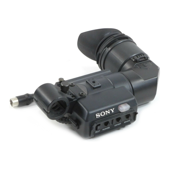
• DXF-701WS/701WSCE The DXF-701/701CE is an electronic (monochrome) The DXF-701WS/701WSCE is an electronic viewfinder which can be attached to a Sony CCD Color (monochrome) viewfinder which can be attached to a Sony Video Camera DXC-D30/D30P. For details of operation, CCD Color Video Camera DXC-D30/D30P/D30WS/ refer to the Operating Instructions for the camera. -
Page 6: Service Information
1. Remove four screws as shown in Figure and remove 3. Untie two strings and remove an adhesive tape and the bottom case. Cable Holder. Screws(B3 X 8) Screws(B3 X 8) String String Adhesive tape Bottom case Cable holder 2-1 (E) DXF-701 (UC) DXF-701CE (CE) -
Page 7: Replacement Of Vf Loupe
CRT/DY Ass'y Friction spring 3. Remove one side of cutout portion as shown in Figure. Pull out the lens holder (2) and remove the VF loupe. Projection Mark VF loupe Lens holder(2) Convexity Cutout DXF-701 (UC) 2-2 (E) DXF-701CE (CE) -
Page 8: Replacement Of Outside Holder T And Eyepiece Outer Ring
There are two kind of VF loupes as optional accesory. Use a VF loupe to match your visibility range. VF loupe for aged eyes; –2D to +1D (Sony part No. 3-725-276-01) –0.5D to +3D (Sony part No. 3-176-501-01) (For reference) Standard ; –3D to 0D 2-4. -
Page 9: Alignment
1. This “ALIGNMENT” is used for the adjustment of 1. Pattern box PTB-500 DXF-701/701CE and DXF-701WS/701WSCE. Sony part number J-6029-140-B 2. Resolution chart Therefore, when adjusting DXF-701/701CE, use the Sony part number J-6026-100-A video camera DXC-D30/D30P. 3. White Window chart Also, in case of DXF-701WS/701WSCE, use the video 4. -
Page 10: Viewfinder System Adjustment
If not met the specification, adjust 1RV4(VH-ADJ)/ MAIN board. (VH-ADJ) (VO-ADJ) (H-SIZE) (FOCUS) RV14 (OPAMP-ADJ) RV15 (V-SIZE : WIDE) (DXF-701WS/701WSCE only) TP12 TP11 (V-SIZE) (V-LINE) (V-HOLD) (H-HOLD) TP10 MAIN BOARD -COMPOMENT SIDE- MAIN BOARD -SOLDERING SIDE- DXF-701 (UC) 3-2 (E) DXF-701CE (CE) -
Page 11: Horizontal Hold Adjustment
(VH-ADJ) (VO-ADJ) (H-SIZE) (FOCUS) RV14 (OPAMP-ADJ) RV15 (V-SIZE : WIDE) (DXF-701WS/701WSCE only) TP12 TP11 (V-SIZE) (V-LINE) (V-HOLD) (H-HOLD) TP10 MAIN BOARD -SOLDERING SIDE- MAIN BOARD -COMPOMENT SIDE- DXF-701 (UC) 3-3 (E) DXF-701CE (CE) -
Page 12: Picture Frame Adjustment
6. Repeat procedure 2 to 4 until the specification are met. and this adjustment affect each other. Repeat these adjustments until both specifications are Note: In case of the adjustment for DXF-701/701CE, met. Also, confirm “3-2-2.Heater Voltage Pre- the adjustment is completed the procedure 1 Adjustment”. -
Page 13: Bright Calibration Adjustment
RV12 (PEAK-OFFSET) (SUB-BRIGHT) SUB BOARD -COMPOMENT SIDE- (VH-ADJ) (VO-ADJ) (H-SIZE) (FOCUS) RV14 (OPAMP-ADJ) RV15 (V-SIZE : WIDE) (DXF-701WS/701WSCE only) TP12 (V-SIZE) (V-LINE) (V-HOLD) (H-HOLD) TP11 TP10 MAIN BOARD -COMPOMENT SIDE- MAIN BOARD -SOLDERING SIDE- DXF-701 (UC) 3-5 (E) DXF-701CE (CE) -
Page 14: Peaking Offset Adjustment
RV12 (PEAK-OFFSET) (SUB-BRIGHT) SUB BOARD -COMPOMENT SIDE- (VH-ADJ) (VO-ADJ) (H-SIZE) (FOCUS) RV14 (OPAMP-ADJ) RV15 (V-SIZE : WIDE) (DXF-701WS/701WSCE only) TP12 TP11 (V-SIZE) (V-LINE) (V-HOLD) (H-HOLD) TP10 MAIN BOARD -SOLDERING SIDE- MAIN BOARD -COMPOMENT SIDE- DXF-701 (UC) 3-6 (E) DXF-701CE (CE) - Page 15 http://getMANUAL.com...
-
Page 16: Block Diagram
SECTION 4 BLOCK DIAGRAM 120ns BUFF DELAY L2,C64 CN100 CONTRAST (MALE) -EXTERNAL SIDE- LED1 LED2 DRIVER TALLY REC IND MAIN BUFF TOP VIEW IC6,Q5 +9.5V TO Q11,IC11 VO-ADJ TO IC1,IC2,IC3,IC4,IC5,Q2,Q3,Q4 IC1(1/3) IC1(2/3) SYNC BUFF DETECT DXF-701 (J, UC) DXF-701CE (CE) - Page 17 LED4 BUFF 10-2 TAKE/GREEN D2,Q2 BUFF LED5 10-3 REC/TALLY SHIFT BUFF REGISTER IC3(1/2) IC5(1/2) LED(B) IC3(2/2) BUFF LED6 11-1 GAIN UP IC4(1/2) LED7 IC1(3/3) 11-2 SHUTTER IC5(2/2) LED8 IC4(2/2) BUFF 11-2 REC(B) OVERALL BLOCK B-DXF701WS-OABLOCK/M DXF-701 (J, UC) DXF-701CE (CE)
-
Page 18: Schematic Diagram And Board Layouts
MAIN SECTION 5 SCHEMATIC DIAGRAM AND BOARD LAYOUTS MAIN BOARD DXF-701 DXF-701CE -A SIDE- -B SIDE- DXF-701 (J,UC) DXF-701CE (CE) - Page 19 MAIN DXF-701WS DXF-701WSCE -A SIDE- -B SIDE- DXF-701 (J,UC) DXF-701CE (CE)
-
Page 20: Sub Board
SUB BOARD -A SIDE- -B SIDE- DXF-701 (J,UC) DXF-701CE (CE) -
Page 22: Frame
IC3(1/2) IC4(2/2) IC5(1/2) TC7W00F TC7W00F TC7W00F IC3(2/2) IC4(1/2) IC5(2/2) TC7W00F TC7W00F TC7W00F TC74HC595P 2SC4081 IMX1 IMZ1 2SC4081 2.2k 1.5k 2.2k DAN202U 4.7k 1.5k RESET 2.2k 1.5k 2.2k DAP202U 2.2k IC1(1/3) IC1(2/3) IC1(3/3) TC7W04F TC7W04F TC7W04F DXF-701 (J, UC) DXF-701CE (CE) - Page 23 R153 R136 2.2k R147 1.6k R157 R138 R139 R140 R155 R158 4.7k R146 R148 200 (FOR DXF-701) 2SC4081 500 (FOR DXF-701WS/701WSCE) 560p (FOR DXF-701) 220p (FOR DXF-701WS/701WSCE) IC11 3.3k HA11423MP 5600p(FOR DXF-701) (1/2) R100 NO MOUNT(FOR DXF-701WS/701WSCE) 4.7k R107 10 (FOR DXF-701)
-
Page 24: Semiconductor Pin Assignments
2SB1115A-YQ IMX1 ; ORANGE RLS245 2SB1132-R CL-150UR-CD-T CATHODE ; RED MARK CL-150D-CD-T -TOP VIEW- DAN202U HZK4ALL 2SB1201 HZK9CL -TOP VIEW- IMZ1 -TOP VIEW- -TOP VIEW- -TOP VIEW- DAP202U SC802-04 2SC4081-R 2SC4102 2SC4178-F13 2SK1113 ESJA57 V09C DXF-701 (J, UC) DXF-701CE (CE) - Page 25 C-MOS DUAL BILATERAL SWITCH X-RAY TRIGG (SCALE 3/1) V BLKG OUT —TOP VIEW— BLKG TRIGG (+3 to +18V) V DEF OUT DRIVER SIZE IN/OUT IN/OUT GND 4 CONTROL CONTROL SWITCH 0 ; LOW LEVEL 1 ; HIGH LEVEL DXF-701 (J, UC) DXF-701CE (CE)
- Page 26 Y = A • B = A + B 0; LOW LEVEL 1; HIGH LEVEL TC7WU04F (TOSHIBA)CHIP PACKAGE C-MOS HEX INVERTERS (SCALE 3/1) —TOP VIEW— DD(+2 to +6V) GND 4 Y = A 0 ; LOW LEVEL 1 ; HIGH LEVEL DXF-701 (J, UC) DXF-701CE (CE)
-
Page 27: Spare Parts
Therefore, specified parts should be used in the case of replacement. (2) Standardization of Parts Repair parts supplied from Sony Parts Center may not be always identical with the parts which actually in use due to “accommodating the improved parts and/or engineering changes”... -
Page 28: Exploded Views
3-165-904-01 s WASHER, SCREW STOPPER 9-933-337-01 o SPRING(1), HINGE 3-176-022-03 o SPACER(B), MASK 9-933-338-01 o SPRING(2), HINGE 3-678-684-01 s HOLDER, CABLE 9-933-339-01 o MIRROR 3-680-605-00 o CAP, SLIDE 9-933-340-02 s HOLDER B, OUTSIDE 3-686-264-02 s EYECAP(3) DXF-701 (J, UC) DXF-701CE (CE) - Page 29 9-880-270-01 o SHEET, BOSS FASE AD 9-933-349-01 s WASHER 9-939-449-01 s ORNAMENTAL PLATE, MASK 9-939-451-01 o MOUNTED CIRCUIT BOARD, LED(A) 9-939-453-02 o MOUNTED CIRCUIT BOARD, LED(B) 9-939-454-02 o CASE, BOTTOM 9-939-455-11 s HARNESS (13-CORE) 9-994-820-01 o RING, SLIDE DXF-701 (J, UC) DXF-701CE (CE)
-
Page 30: Electrical Parts List
------------ Ref. No. ! 1-589-908-11 s MOUNTED CIRCUIT BOARD, MAIN or Q'ty Part No. SP Description (for DXF-701) ! 1-589-908-21 s MOUNTED CIRCUIT BOARD, MAIN 9-933-451-01 s PRINTED CIRCUIT BOARD, LED(A) (for DXF-701CE) 9-933-312-01 s HARNESS (4-CORE) ! 1-589-908-31 s MOUNTED CIRCUIT BOARD, MAIN... - Page 31 9-904-851-01 s TANTALUM, CHIP 10uF 20% 16V 8-729-905-38 s TRANSISTOR 2SC4081T106R 1-163-018-00 s CERAMIC, CHIP 5600pF 10% 50V 8-729-117-72 s TRANSISTOR 2SC4178 (for DXF-701/701CE) 8-729-905-38 s TRANSISTOR 2SC4081T106R 9-980-618-01 s ELECT 220uF 20% 6.3V 8-729-907-46 s TRANSISTOR IMZ1 1-163-251-00 s CERAMIC, CHIP 100pF 5% 50V...
- Page 32 1-216-049-11 s METAL, CHIP 1K 5% 1/10W 9-933-319-01 s RES, VAR METAL 200 ! 1-216-077-00 s METAL, CHIP 15K 5% 1/10W (for DXF-701/701CE) ! 1-216-077-00 s METAL, CHIP 15K 5% 1/10W 9-933-320-01 s RES, VAR METAL 500 1-216-121-00 s METAL, CHIP 1M 5% 1/10W...
- Page 33 1-216-042-00 s METAL, CHIP 510 5% 1/10W R121 1-216-042-00 s METAL, CHIP 510 5% 1/10W R122 1-216-055-11 s METAL, CHIP 1.8K 5% 1/10W R123 1-216-055-11 s METAL, CHIP 1.8K 5% 1/10W R124 1-216-063-00 s METAL, CHIP 3.9K 5% 1/10W DXF-701(J,UC) DXF-701CE(CE)
- Page 35 http://getMANUAL.com...
- Page 36 DXF-701 (J, UC) DXF-701CE (EK) Printed in Japan DXF-701WS (J, UC) Sony Corporation 1997. 12 08 DXF-701WSCE (CE) Image & Sound Communication Company 9-977-265-02 ©1996 Published by Engineering Services Dept.
Need help?
Do you have a question about the DXF-701 and is the answer not in the manual?
Questions and answers