Table of Contents
Advertisement
Quick Links
Advertisement
Table of Contents

Related Manuals for Sony DXF-20W


Summary of Contents for Sony DXF-20W
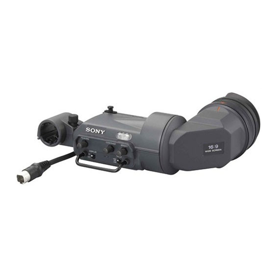
- Page 1 ELECTRONIC VIEWFINDER DXF-20W SERVICE MANUAL 1st Edition...
- Page 2 Pour toute réparation faire appel à une personne compétente uniquement. X-RAY RADIATION WARNING Be sure that parts replacement in the high voltage block and adjustments made to the high voltage circuits are carried out precisely in accordance with the procedures given in this manual. DXF-20W...
-
Page 3: Table Of Contents
Horizontal Shift Adjustment (For PAL) ..2-6 (E) 2-2-7. Vertical Frame Adjustment (For NTSC) ..2-7 (E) 2-2-7. Vertical Frame Adjustment (For PAL) ..2-8 (E) 2-2-8. Screen Centering Check ......... 2-9 (E) 2-2-9. Vertical Linearity Adjustment ......2-9 (E) 1 (E) DXF-20W... -
Page 4: Manual Structure
Manual Structure Purpose of this manual This manual is the service manual for Electronic Viewfinder DXF-20W. This manual describes the information items necessary when the unit is supplied and installed, items on maintenance, and items that premise the service based on the components parts such as alignment, schematic diagrams, board layouts and spare parts list, assuming use of system and service engineers. -
Page 5: Service Overview
ON : 0 ± 0.5 V sometimes by visual, and replace as necessary. VF VIDEO (X) V = 1.0 V p-p Name Sony Part No. EXT. DC (12 V) 10.6 V to 17.0 V dc Gel, MIC 3-854-132-0X EYE CUP KIT (RP) -
Page 6: Cleaning
. To protect the viewfinder lens from drops, put the MC protector in the filter holder and attach the eyecup securely. Align red lines Hold ring MC protector VF tube sub assembly Filter holder Eyecup 1-2 (E) DXF-20W... -
Page 7: Replacing Crt/Dy Assembly
5. Cut the binding yarn of the high-voltage cable. 6. Disconnect the high-voltage cable connector. 7. Disconnect the harnesses from the connectors CN4, CN5, and CN6 on the VF-88 board. Harnesses CRT/DY assembly Binding yarn High-voltage cable connector VF-88 board 1-3 (E) DXF-20W... -
Page 8: Arranging Harness
1. Arrange the 8-wire harness as shown in the figure and clamp it at point A so that it is not in contact with the inside of the VF tube assembly or the lower chassis. 8-wire harness VF tube assembly Lower chassis VF cable High-voltage cable 1-4 (E) DXF-20W... -
Page 9: Disconnecting/Connecting Flexible Card Wire
2. Slide portions A in the reverse direction to lock. Tape Conductive surface High-voltage cable 8. Install the upper chassis. Be careful so that the high-voltage cable is not caught. 1-5 (E) DXF-20W... -
Page 10: Notes On Spare Parts
2. Standardization of Parts : LEAD FREE MARK Some spare parts supplied by Sony differ from those used for the unit. These are because of parts common- ality and improvement. -
Page 11: Alignment
Alignment 2-1. Preparation 2-1-2. Required Equipment 2-1-1. Connecting Diagram Tools/measuring equipment . Pattern box PTB-500 (Sony part number: J-6029-140-B) Using a video camera . Resolution chart (4:3) (Sony part number: J-6026-100-A) . Resolution chart (16:9) (Sony part number: J-6395-320-A) DXF-20W PTB-500 . -
Page 12: Viewfinder System Adjustment
OUT connector on the camera is as follows. For NTSC: 100 ± 2 IRE 700 ± 14 mV For PAL: VF-88 board 4. Adjust 1RV3 (FOCUS)/VF-88 board so that the picture on the viewfinder screen is best focused. VF-88 board 2-2 (E) DXF-20W... -
Page 13: Horizontal Frame Adjustment
4. Adjust 1RV2 (H-SIZE WIDE)/VF-88 board so that H size of resolution chart is underscanned by approxi- mately 2 mm from the CRT picture frame. Underscan monitor frame 2 mm (H size) Chart frame Viewfinder screen VF-88 board 2-3 (E) DXF-20W... -
Page 14: Heater Voltage Adjustment
(SUS-BRIGHT: 4:3) / the VA-229 board clockwise from the counterclockwise maximum point. Set the aspect ratio to 16:9 mode again. Adjust 1RV206 (SUS-BRIGHT: 16:9) / the VA-229 board in the same way as the 4:3 mode. VF-88 board RV206 RV204 VF-88 board VA-229 board 2-4 (E) DXF-20W... -
Page 15: Horizontal Shift Adjustment (For Ntsc)
5. Adjust the BRIGHT control fully clockwise and the CONTRAST control fully counterclockwise to display the pedestal portion. 6. Adjust 1RV101 (H-SHIFT: N)/DF-70 board so that the pedestal portion on both sides are equal. Pedestal portion on both sides are equal. Viewfinder screen DF-70 board 2-5 (E) DXF-20W... -
Page 16: Horizontal Shift Adjustment (For Pal)
5. Adjust the BRIGHT control fully clockwise and the CONTRAST control fully counterclockwise to display the pedestal portion. 6. Adjust 1RV102 (H-SHIFT: P)/DF-70 board so that the pedestal portion on both sides are equal. Pedestal portion on both sides are equal. Viewfinder screen DF-70 board 2-6 (E) DXF-20W... -
Page 17: Vertical Frame Adjustment (For Ntsc)
5. Adjust 1RV103 (V-SIZE: N)/DF-70 board so that the V size of resolution chart is underscanned by approxi- mately 2 mm from the CRT picture frame. CRT frame Chart frame Approx. 2 mm (V size) Viewfinder screen DF-70 board 2-7 (E) DXF-20W... -
Page 18: Vertical Frame Adjustment (For Pal)
(When 1RV104 is not adjusted, the adjustment may not be performed by just 1RV103. In such case, adjust 1RV103 after roughly adjusting by 1RV104.) CRT frame Chart frame Approx. 2 mm (V size) Viewfinder screen DF-70 board 2-8 (E) DXF-20W... -
Page 19: Screen Centering Check
Check that the image is in the center when it is viewed through the viewfinder in the normal state. If the image is not in the center, perform the centering magnet adjustment to adjust the image to the center. VF tube Top chassis Centering magnet DF-70 board 2-9 (E) DXF-20W... -
Page 21: Spare Parts
7-621-772-18 s SCREW +B M2X4 3-685-104-01 s NUT(M6),CONTROL (STEEL) 3-692-132-03 o COVER,TALLY 7-624-102-04 s STOP RING 1.5 TYPE-E 7-627-454-38 s SCREW, PRECISION +K2.6X5 3-692-134-01 o MIC CLAMP 3-692-147-01 o GUARD BAR 7-683-412-05 s BOLT,HEXAGON SOCKET 2.6X6 (ST) 7-685-134-19 s SCREW +PTP2.6X8(EP-FE/ZNBK/CM2) DXF-20W... - Page 22 3-692-136-03 s FIXED RING 7-627-553-78 s SCREW,PRECISION +P 2X10 3-692-139-01 s MIRROR(2) 7-671-158-01 s BALL, STAINLESS (2.5 DIA) 3-697-151-01 s RING,VF 7-685-104-19 s SCREW +PTP 2X6 (EP-FE/ZNBK/CM2) 7-685-134-19 s SCREW +PTP 2.6X8 (EP-FE/ZNBK/CM2) 3-697-154-01 s HOLDER,MIRROR(3) 3-991-417-01 s PLATE A,DISPLAY DXF-20W...
-
Page 23: Electrical Parts List
SP Description 9-885-107-93 s MOUNTED CIRCUIT BOARD, VF-88 1-576-805-11 s FUSE (SMD/FAST ACTING) 9-885-107-19 s FLYBACK TRANSFORMER 9-885-083-37 s COIL, HORIZONTAL LINEARITY 9-885-107-20 s REGULATOR CONTROL IC 9-885-083-50 s COIL, INDUCTOR 1-762-488-11 s SWITCH, TOGGLE 1-762-489-11 s SWITCH, TOGGLE DXF-20W... -
Page 25: Block Diagram
21-1 BATT BUFF TALLY GREEN 21-3 TALLY(GREEN) D1,Q1 BUFF REC(T) 21-2 TALLY/REC IC2,Q4 SHIFT SHUTTER SHUTTER REGISTER GAIN UP GAIN UP BUFF GAIN UP +9.5V 21-8 GAIN UP FUSE SHUTTER TO IC5 21-6 SHUTTER REC(B) 21-7 REC(B) VF-88 Overall DXF-20W... - Page 27 6.3V C137 C138 V•BLK C133 C•BLK1(9.5V SWING) 0.1u 0.1u 0.1u 430k R151 R153 or 390k SYNC VIDEO 5.1k C130 or 470k 0.1u C128 or 510k R150 C129 SYNC SEP. SYNC SEP. 470k 1000p IC109B LM5110-1MX DF-70 BOARD NO. 1-868-570-11 DXF-20W...
- Page 28 RV204:SUB BRIGHTNESS RV205:BRIGHTNESS RV206:SUB BRIGHT (WIDE) R241 R244 R242 2125 R239 R238 R240 C211 IC201A 4.7u RV202 NJM2904M 10KB C210 Q213 C209 C4178 3.3u C212 0.01u R245 1608 R243 R246 IC201B 1608 NJM2904M 2125 VA-229 BOARD NO. 1-868-571-11 RV202:PEAKING DXF-20W...
- Page 29 +H.DEF OUT L:CH0 0.1u -V DEF -V.DEF OUT -V.DEF OUT (16:9) K1254 H:CH1 +V.DEF OUT +V.DEF OUT (4:3) IC6 TC4S69F 5600p DY<6400-14F-2> 100V P.P.C V.DY K1254 RD6.2UJN-T1 0.1u 100B LC37-34F TC4S01F VF-88 RV5:H-LIN BOARD NO. 1-868-569-11 LE-326 BOARD NO. 1-868-572-11 DXF-20W...
- Page 31 DF-70, VA-229 DF-70, VA-229 Section 6 Board Layouts DF-70 VA-229 SUFFIX: -11 SUFFIX: -11 DXF-20W...
- Page 32 VF-88 VF-88 VF-88 VF-88 SUFFIX: -11 SUFFIX: -11 DXF-20W...
- Page 34 Printed in Japan Sony Corporation 2006. 5 08 DXF-20W (SY) J, E 9-968-256-01 ©2006...
- Page 35 7-621-772-18 s SCREW +B M2X4 3-685-104-01 s NUT(M6),CONTROL (STEEL) 3-692-132-03 o COVER,TALLY 7-624-102-04 s STOP RING 1.5 TYPE-E 7-627-454-38 s SCREW, PRECISION +K2.6X5 3-692-134-01 o MIC CLAMP 3-692-147-01 o GUARD BAR 7-683-412-05 s BOLT,HEXAGON SOCKET 2.6X6 (ST) 7-685-134-19 s SCREW +PTP2.6X8(EP-FE/ZNBK/CM2) DXF-20W...
- Page 36 3-692-136-03 s FIXED RING 7-627-553-78 s SCREW,PRECISION +P 2X10 3-692-139-01 s MIRROR(2) 7-671-158-01 s BALL, STAINLESS (2.5 DIA) 3-697-151-01 s RING,VF 7-685-104-19 s SCREW +PTP 2X6 (EP-FE/ZNBK/CM2) 7-685-134-19 s SCREW +PTP 2.6X8 (EP-FE/ZNBK/CM2) 3-697-154-01 s HOLDER,MIRROR(3) 3-991-417-01 s PLATE A,DISPLAY DXF-20W...
Need help?
Do you have a question about the DXF-20W and is the answer not in the manual?
Questions and answers