
Related Manuals for Global Test Supply 3284


Summary of Contents for Global Test Supply 3284
- Page 1 All manuals and user guides at all-guides.com 3284 CLAMP ON AC/DC HiTESTER INSTRUCTION MANUAL GlobalTestSupply www. .com Find Quality Products Online at: sales@GlobalTestSupply.com...
-
Page 2: Table Of Contents
All manuals and user guides at all-guides.com Contents Introduction Shipping Check Safety Attentions During Use Organization of This Manual Chapter 1 Product Outline 1.1 Product Outline 1.2 Features 1.3 Parts and Functions 1.4 Flowchart of Key Operations 1.4.1 Current Measurements Mode 1.4.2 Voltage Measurements Mode 1.4.3 Frequency Measurements Mode 1.5 Modes... - Page 3 All manuals and user guides at all-guides.com 2.3.4 Peak Hold Measurement 2.4 Frequency Measurement 2.4.1 Frequency Measurement in Current Mode 30 2.4.2 Frequency Measurement in Voltage Mode 31 2.4.3 Output Function For Frequency 2.5 Auto-Zero-Adjustment/ Zero-Cancel Correction Function 2.5.1 Auto-Zero-Adjustment Function 2.5.2 Zero-Cancel Correction Function 2.6 Data Hold Function HOLD...
- Page 4 All manuals and user guides at all-guides.com Introduction Thank you for purchasing this HIOKI "3284 CLAMP ON AC/DC HiTESTER." To get the maximum performance from the unit, please read this manual first, and keep this at hand. Request We have tried to bring this manual as close to perfection as we could achieve.
-
Page 5: Shipping Check
If the unit is damaged, or fails to operate according to the specifications, contact your dealer or HIOKI representative. Check the 3284 Unit and the Supplied Accessories Main unit 3284 CLAMP ON AC/DC HiTESTER Supplied accessories... -
Page 6: Safety
All manuals and user guides at all-guides.com Safety DANGER This equipment is designed according to IEC 1010 Safety Standards, and has been tested for safety prior to shipment. Incorrect measurement procedures could result in injury or death, as well as damage to the equipment. Please read this manual carefully and be sure that you understand its contents before using the equipment. - Page 7 All manuals and user guides at all-guides.com The following symbols are used in this Instruction Manual to indicate the relative importance of cautions and warnings. Indicates that incorrect operation presents extreme danger of accident DANGER resulting in death or serious injury to the user. ...
- Page 8 All manuals and user guides at all-guides.com Safety Symbols This symbols is affixed to locations on the unit where the operator should consult corresponding topics in this manual (which are also marked with the symbol) before using relevant functions of the unit. In the manual, this mark indicates explanations which it is particularly important that the user read before using...
-
Page 9: Attentions During Use
All manuals and user guides at all-guides.com Attentions During Use In order to ensure safe operation and to obtain maximum performance from the unit, observe the cautions listed below. DANGER ・ ・ ・ ・ Use clamp testers only on power lines up to 600 Vrms AC, to avoid short-circuits and accidents that could result in injury or death. - Page 10 All manuals and user guides at all-guides.com WARNING ・ ・ ・ ・ To prevent electric shock, do not allow the unit to become wet and do not use the unit when your hands are wet. ・ ・ ・ ・ To avoid electric shock accidents, when carrying out measurement on live lines, wear proper protective gear, including insulating rubber gloves, insulating rubber boots, and...
- Page 11 All manuals and user guides at all-guides.com viii CAUTION ・ Do not store or use the unit where it will be exposed to direct sunlight, high temperature, high humidity, or condensation. If exposed to such conditions, the unit may be damaged, the insulation may deteriorate, and the unit may no longer satisfy its specifications.
- Page 12 All manuals and user guides at all-guides.com CAUTION ・ Do not use the unit if the battery is exhausted (when mark lights in the display area). Be sure to replace the exhausted battery with a new one. ・ When replacing the battery, make sure that the metal battery snap fitting is firmly connected.
-
Page 13: Organization Of This Manual
Organization of This Manual Chapter 1 Product Outline Explains the parts and functions of the unit. Chapter 2 Measurement Procedure Explains how to use the 3284 for measurement. Chapter 3 Specifications Lists the specifications of the 3284 CLAMP ON AC/DC HiTESTER. Chapter 4... -
Page 14: Chapter 1 Product Outline
All manuals and user guides at all-guides.com Chapter 1 Product Outline 1.1 Product Outline The 3284 CLAMP ON AC/DC HiTESTER makes it possible to measure DC, AC or AC+DC current in live power lines without tapping into or connecting the lines. Using a one-chip microprocessor, the... -
Page 15: Features
All manuals and user guides at all-guides.com 1.2 Features ・ A multi-function microcomputer The built-in microcomputer offers various functions in a compact form. ・ Display of true rms values The true rms value conversion circuit allows accurate measurement of currents with distorted waveforms. -
Page 16: Parts And Functions
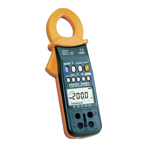
All manuals and user guides at all-guides.com 1.3 Parts and Functions Top and Side View ⑩ ⑰ ① ② ⑪ ③ ⑱ ④ ⑤ ⑥ ⑨ ⑧ ⑦ ⑫ ⑭ ⑯ ⑬ ⑮ GlobalTestSupply www. .com Find Quality Products Online at: sales@GlobalTestSupply.com Chapter 1 Product Outline... - Page 17 All manuals and user guides at all-guides.com ① POWER ・ Used to turn power on/off ・ To disable the auto power-off function, hold HOLD and press , when you turn power on. POWER ② ・ Switches current modes as follow. DCA...
- Page 18 All manuals and user guides at all-guides.com ⑥ SLOW/PEAK/Hz ・ SLOW slows down screen updating (once per three seconds). ・ FAST speeds up screen updating (four times per second). There isn't an annunciator " ". FAST Instead, the unit symbol blinks. ・...
- Page 19 All manuals and user guides at all-guides.com ⑨ 0ADJ/RESET ・ Performs auto-zero-adjustment in DC A, AC+DC A and DC V modes. ・ Resets data when measuring peak values. Reset all the data in a REC function. ・ If zero is not indicated under no input in the AC A, AC+DC A, AC V or AC+DC V modes, press , then press to perform a zero-...
- Page 20 All manuals and user guides at all-guides.com ⑫ Display (LCD) Direct Current (DC) Alternating Current (AC) Alternating Current and Direct Current (AC+DC) Auto-zero-adjustment or zero-cancel correction function is active Battery low warning Data hold function HOLD Waveform output (AC) is active Recording output (DC) is active Auto power off function AUTO...
- Page 21 All manuals and user guides at all-guides.com Current hour 1 hour/segment (bar graph) 1 minute/segment (bar graph) Input over (bar graph) ⑬ Output terminal Connected to the optional 9094 output cord to provide output during a current measurement or a frequency measurement in a current mode.
-
Page 22: Flowchart Of Key Operations
All manuals and user guides at all-guides.com 1.4 Flowchart of Key Operations 1.4.1 Current Measurements Mode DC A AC A AC+DC A RANGE key AUTO range AUTO range AUTO range 20.00 A range 20.00 A range 20.00 A range 200.0 A range 200.0 A range 200.0 A range SLOW/PEAK/... -
Page 23: Voltage Measurements Mode
All manuals and user guides at all-guides.com 1.4.2 Voltage Measurements Mode V key DC V AC V AC+DC V RANGE key AUTO range AUTO range AUTO range 30.00 V range 30.00 V range 30.00 V range 300.0 V range 300.0 V range 300.0 V range 600 V range 600 V range... -
Page 24: Frequency Measurements Mode
All manuals and user guides at all-guides.com 1.4.3 Frequency Measurements Mode Current (AC A, AC+DC A) mode Voltage (AC V, AC+DC V) mode SLOW/PEAK/ SLOW FAST PEAK Hz key Current mode Voltage mode RANGE key AUTO range AUTO range 10.00 Hz range 10.00 Hz range 100.0 Hz range 100.0 Hz range... -
Page 25: Modes
All manuals and user guides at all-guides.com 1.5 Modes For voltage and current, three modes are provided: DC (direct current, ), AC (alternating current, and AC+DC (alternating current and direct current, ) modes. Select a proper mode according to the waveform shown below: GlobalTestSupply www. - Page 26 All manuals and user guides at all-guides.com OUTPUT Input Mode Display (only for current mode) waveform ○Average value displayed (with polarity) Disabled ×Not measurable ( ) ×Not measurable ×Not measurable (zero displayed) ○RMS value ( ) ×Not measurable ○RMS value (without polarity) AC+DC ○RMS value...
-
Page 27: Chapter 2 Measurement Procedure
All manuals and user guides at all-guides.com Chapter 2 Measurement Procedure 2.1 Preparations 1. Remove the rear cover and insert a battery. (Refer to "Chapter4 Battery Replacement".) 2. Press to turn the unit on. Verify that all POWER segments of the display light up briefly. Then the model name is shown, and the bar graph indicates the battery condition. -
Page 28: Current Measurement
All manuals and user guides at all-guides.com 2.2 Current Measurement ・ Accurate measurement may be impossible in NOTE locations subject to strong external magnetic fields, such as transformers and high-current conductors, or in locations subject to strong external electric fields, such as radio transmission equipment. -
Page 29: Measuring Ac Current (Ac A)
All manuals and user guides at all-guides.com Wrong Measured conductor Current direction Current direction indicator ・ The DC A mode permits only pure DC current NOTE measurements (see 1.5: Modes). ・ The 20 A range will display up to 25 A, however, only the range from 1 A to 20 A can be displayed with guaranteed accuracy. -
Page 30: Measuring Ac/Dc Current (Ac+Dc A)
All manuals and user guides at all-guides.com ・ Depending on ambient temperatures, the counter NOTE would not become zero under no input. If this happens, perform a zero-cancel correction (2.5.2: Zero-cancel correction function). ・ The measurement response speed is about 250 ms during rise (0% to 90%) and about 500 ms (100% to 10%) during fall (2.2.5, Figs. - Page 31 All manuals and user guides at all-guides.com 5. Open the top ends of the clamp core and clamp the measured conductor so that it passes through the center of the clamp core. ・ Just after suspension of input, or when modes are NOTE switched under no input, the counter would not become zero for about 10 seconds.
-
Page 32: Peak Hold Measurement
All manuals and user guides at all-guides.com 2.2.4 Peak Hold Measurement 1. Press and select a measurement mode for the measured circuit. 2. In DC A and AC+DC A modes, make an auto-zero- adjustment by 0ADJ/RESET 3. Set to PEAK. The measurement mode is switched as follows. -
Page 33: Output Function
All manuals and user guides at all-guides.com ・ In case that the counter doesn't become zero under NOTE no input in peak measurement mode, even though you pressed to reset the peak data, the 0ADJ/RESET clamp sensor may be magnetized. Quit the peak measurement mode, and perform the auto-zero adjustment by . - Page 34 All manuals and user guides at all-guides.com switches the output modes. OUTPUT REC (Record output) MON (Waveform output) Light turned off (Auto power-off inactive) (Auto power-off inactive) (Auto power-off active) 4. Set a range based on the unit's measurement range and other instruments, such as recorders.
- Page 35 All manuals and user guides at all-guides.com ・ outputs are analog outputs. The output NOTE response time during an f.s. input differs between rise (0% to 90%, about 250 ms) and fall (100% to 10%, about 500 ms). (Figs 2 and 3) ・...
- Page 36 All manuals and user guides at all-guides.com GAIN [dB] AC+DC A (MON) ‑2 AC A (MON) ‑4 ‑6 ‑8 ‑10 ‑12 ‑16 ‑18 100m 100k FREQUENCY [Hz] Fig. 1 Frequency Characteristics of Current Output GlobalTestSupply www. .com Find Quality Products Online at: sales@GlobalTestSupply.com Chapter 2 Measurement Procedure...
- Page 37 All manuals and user guides at all-guides.com Input wave Output wave 20 A 10 A 250 ms Fig. 2 Waveform of Output Response (Rise) Input wave Output wave 500 ms Fig. 3 Waveform of Output Response (Fall) GlobalTestSupply www. .com Find Quality Products Online at: sales@GlobalTestSupply.com Chapter 2...
-
Page 38: Voltage Measurement
All manuals and user guides at all-guides.com 2.3 Voltage Measurement 2.3.1 Measuring DC Voltage (DC V) 1. Press to display 2. Slide the slide cover up using the slide knob. Next, insert the red test lead to V and the black test lead to COM of the voltage measurement terminal. -
Page 39: Measuring Ac Voltage (Ac V)
All manuals and user guides at all-guides.com 2.3.2 Measuring AC Voltage (AC V) to display 〜. 1. Press 2. Slide the slide cover up using the slide knob. Next, insert the red test lead to V and the black test lead to COM of the voltage measurement terminal. -
Page 40: Measuring Ac/Dc Voltage (Ac+Dc V)
All manuals and user guides at all-guides.com 2.3.3 Measuring AC/DC Voltage (AC+DC V) 1. Press to display 2. Slide the slide cover up using the slide knob. Next, insert the red test lead to V and the black test lead to COM of the voltage measurement terminal. - Page 41 All manuals and user guides at all-guides.com 2.3.4 Peak Hold Measurement 1. Press and select a measurement mode for the measured circuit. (No auto-zero-adjustment is necessary in any voltage mode.) 2. Slide the slide cover up using the slide knob. Next, insert the red test lead to V and the black test lead to COM of the voltage measurement terminal.
- Page 42 All manuals and user guides at all-guides.com 2.4 Frequency Measurement 2.4.1 Frequency Measurement in Current Mode 1. Press and select AC or AC+DC, depending on the circuit to be measured. 2. If the current range of the measured circuit is known, set the current range to the manual range.
- Page 43 All manuals and user guides at all-guides.com ・ The 10 Hz range or 100 Hz range will display up to NOTE 125% of each range, however, only the range from 10% to 100% can be displayed with guaranteed accuracy. ・ does not affect output values.
- Page 44 All manuals and user guides at all-guides.com ・ At the 100 Hz and 1000 Hz ranges, ---- appears on NOTE the counter when the frequency is lower than 10 Hz. ・ ---- appears on the counter, if the frequency is lower than 1 Hz.
- Page 45 All manuals and user guides at all-guides.com 2. Press annunciator lights and OUTPUT activates the output function. 3. The auto power-off function is automatically disabled. ( annunciator is tuned off.) 4. Set a range based on the unit's measurement range and other instruments, such as recorders.
- Page 46 All manuals and user guides at all-guides.com ・ For a long term measurement, use the optional 9445 NOTE AC adapter. ・ When the AC adapter is used and there is a large amount of noise in the power line, the display may show several counts or noise may be present in the output.
- Page 47 All manuals and user guides at all-guides.com ・ If you press again during the auto- 0ADJ/RESET NOTE zero-adjustment in the internal circuit, the auto-zero- adjustment is canceled. 2.5.2 Zero-Cancel Correction Function Use the zero-cancel correction function when the counter fails to become zero under no input in AC A, AC+DC A, AC V, or AC+DC V mode.
- Page 48 All manuals and user guides at all-guides.com 2.7 Alteration of Counter Updates The counter is updated twice per second when powering on. The counter update may be altered according to measurement conditions. changes an annunciator as SLOW/PEAK/Hz follows: SLOW FAST PEAK (The unit (Except DC)
- Page 49 All manuals and user guides at all-guides.com 1. REC annunciator will blink when you press during a current or a voltage MAX/MIN measurement. This function will have stored the measured data in the internal memory since the key is pressed. Only one value will be displayed among these values.
- Page 50 All manuals and user guides at all-guides.com A bar graph segment represents one minute. Up to 59 minutes can be indicated. To change the time scale to hours, press MAX/MIN several times. A segment will now represent one hour. In the following example, one hour and 40 minutes have passed since was pressed.
- Page 51 All manuals and user guides at all-guides.com ・ By pressing any key except , you will POWER extend the powered state for another 10 minutes. Procedure for disabling the auto power-off function. ・ Press with holding down , when POWER HOLD you turn power on.
- Page 52 All manuals and user guides at all-guides.com Chapter 3 Specifications 3.1 Measurement Specifications (23℃ ℃ ℃ ℃ ± ± ± ± 5℃ ℃ ℃ ℃ , 80% RH max.) 3.1.1 Current Measurement Specifications ○ Current display accuracy ① DC current A (mean value) Range Resolution (Accuracy Range)
- Page 53 All manuals and user guides at all-guides.com Range 10〜45,66〜1kHz 1kHz〜2kHz Resolution (Accuracy Range) 200A(100.0〜200.0A) 0.1A ±(2.0%rdg.+7dgt.) ±(4.0%rdg.+7dgt.) ○ Output accuracy ① DC current A (mean value) Range (Accuracy Range) 20A(1.00〜20.00A) 1V/f.s. ±(1.3%rdg.+5mV) 200A(10.0〜200.0A) 1V/f.s. ±(1.3%rdg.+5mV) ② AC current Arms (true rms) Range 45〜66Hz 10〜45,66〜2kHz...
- Page 54 All manuals and user guides at all-guides.com Range 10〜45,66〜1kHz 1kHz〜2kHz (Accuracy Range) 200A(100.0〜200.0A) DC1V/f.s. ±(2.0%rdg.+10mV) ±(4.0%rdg.+10mV) Output response: Rise response time (0% to 90%) 250 ms or less Fall response time (100% to 10%) 500 ms or less ③ AC+DC current Arms (true rms) Range DC,45〜66Hz 10〜45,66〜2kHz...
- Page 55 All manuals and user guides at all-guides.com ○ Peak measurement accuracy (Peak hold function) During continuous input of sine waves ① DC current A peak (wave peak value) Range Resolution (Accuracy Range) 20A(1.0〜50.0A) 0.1A ±(1.3%rdg.+7dgt.) 200A(10.0〜300.0A) 0.1A ±(1.3%rdg.+7dgt.) ② AC current A peak (wave peak value) Range 45〜66Hz 10〜45,66〜2kHz...
- Page 56 All manuals and user guides at all-guides.com Output accuracy Range (Accuracy Range) 10Hz(1.00〜10.00Hz) DC1V/f.s. ±(1.3%rdg.+3mV) DC1V/f.s. ±(1.3%rdg.+3mV) 100Hz(10.0〜100.0Hz) DC1V/f.s. ±(2.0%rdg.+3mV) 1000Hz(100〜1000Hz) Output response: 4 seconds or less at 1000Hz and 100Hz ranges, 6 seconds or less at 10Hz range Current Specifications Maximum permissible 200 Arms continuous, 300 Amax.
- Page 57 All manuals and user guides at all-guides.com 3.1.2 Voltage Measurement Specifications ○ Voltage display accuracy ① DC voltage V (mean value) Range Resolution (Accuracy Range) 30V(3.00〜30.00V) 0.01V ±(1.0%rdg.+3dgt.) 300V(30.0〜300.0V) 0.1V ±(1.0%rdg.+3dgt.) 600V(60〜600V) ±(1.0%rdg.+3dgt.) ② AC voltage Vrms (true rms) Range 45〜66Hz 10〜45,66〜1kHz Resolution...
- Page 58 All manuals and user guides at all-guides.com ③ AC+DC voltage V peak (wave peak value) Range DC,45〜66Hz 10〜45,66〜1kHz Resolution (Accuracy Range) 30V(3.0〜75.0V) 0.1V ±(1.0%rdg.+7dgt.) ±(1.5%rdg.+7dgt.) 300V(30〜750V) ±(1.0%rdg.+7dgt.) ±(1.5%rdg.+7dgt.) 600V(60〜1000V) ±(1.0%rdg.+7dgt.) ±(1.5%rdg.+7dgt.) ○ Frequency measurement Hz Display accuracy Range Resolution (Accuracy Range) 10Hz(1.00〜10.00Hz) 0.01Hz ±(0.3%rdg.+1dgt.)
- Page 59 All manuals and user guides at all-guides.com 3.2 General Specifications ○ Accessory Functions: Auto-zero adjustment 0ADJ/RESET Pressing once in DC A or function AC+DC A mode. Zero cancel function Pressing 0ADJ/RESET once with holding HOLD in AC or AC+DC mode. Recording Maximum (MAX), minimum (MIN), average (AVE) value display selectable...
- Page 60 All manuals and user guides at all-guides.com Display response time Current, Voltage: 1 s max. (the range is fixed, Frequency: 0% to 100%) 1 s max. (1000 Hz, 100 Hz range) 2.5 s max. (10 Hz range) Range switching Auto range, manual (fixed) range (selectable).
- Page 61 All manuals and user guides at all-guides.com Maximum power 110 mVA consumption Battery life Approx. 25 hours (continuous, no load) External dimensions 62(W)×230(H)×39(D) mm 2.44"(W)×9.05"(H)×1.54"(D) Mass Approx. 460 g Approx. 16.2 oz. Accessories 9207 TEST LEAD (red and black) 9399 CARRYING CASE Hand Strap 6F22 (006P) Instruction manual...
- Page 62 All manuals and user guides at all-guides.com Chapter 4 Battery Replacement 1. Remove the two fastening screws of the rear cover, using a Phillips screwdriver. 2. Remove the rear cover. 3. Remove the old battery without pulling the codes of the snap.
- Page 63 All manuals and user guides at all-guides.com Chapter 5 AC Adapter (Optional) Fully insert the optional 9445 AC adapter into the AC adapter connection terminal. ・ The adapter may be used either with or without a NOTE battery. ・ Use of a battery enables continuous measurement if the AC power source temporarily becomes unavailable, due to a blackout or some other reason.
- Page 64 All manuals and user guides at all-guides.com All the phenomena are likely to happen, in the case NOTE the battery voltage is lower than AC adapter voltage (typ. 9 V) . It is recommended that a new battery should be used, when the blackout seems to be short.
- Page 65 All manuals and user guides at all-guides.com Chapter 6 Attaching The Hand Strap Explains how to attach the hand strap, for easy handling of the unit in the field. GlobalTestSupply www. .com Find Quality Products Online at: sales@GlobalTestSupply.com Chapter 6 Attaching The Hand Strap...
- Page 66 All manuals and user guides at all-guides.com Chapter 7 Troubleshooting If the unit seems not to be working normally, check the following points first before requesting service. Repair is required if E.001 to E.005 is indicated on the counter, when power is turned on. ○...
- Page 67 All manuals and user guides at all-guides.com ○ The measured value is smaller than the estimated value. Current measurement: ・ Check that the clamp sensor is firmly closed. ・ Check that the frequency of the measured circuit is within the range provided in the specifications. (A smaller value will be displayed for a high inverter carrier frequency.) ・...
- Page 68 All manuals and user guides at all-guides.com Voltage measurement: ・ Check that the test leads are fully connected. ・ Check that the frequency of the measured circuit is within the range provided in the specifications. ・ Check that the proper steps have been taken, according to the procedure described in 2.5.1: Auto-zero adjustment function and 2.5.2: Zero-cancel correction function.
- Page 69 All manuals and user guides at all-guides.com ○ The measured value is larger than the estimated value. Current measurement: ・ Check that you're using the proper range. ・ Examine the waveform using output function to confirm that no components but the estimated frequency are being used.
- Page 70 All manuals and user guides at all-guides.com ○The output value is smaller than the estimated value. ・ Take the same precautionary steps as for the measured value on the counter. ・ Make sure the 9094 output cord is fully connected. ・...
- Page 71 All manuals and user guides at all-guides.com Chapter 8 Service ・ The minimum stocking period for replacement parts is five years after end of production. ・ For information regarding service, please contact your dealer or the nearest HIOKI representative. ・ If the unit is not functioning properly, check the battery.
- Page 72 All manuals and user guides at all-guides.com GlobalTestSupply www. .com Find Quality Products Online at: sales@GlobalTestSupply.com...
- Page 73 All manuals and user guides at all-guides.com HIOKI 3284 CLAMP ON AC/DC HiTESTER Instruction Manual Publication date: January 2000 Revised edition 2 Edited and published by HIOKI E.E. CORPORATION Technical Support Section All inquiries to Sales and Marketing International Department...
Need help?
Do you have a question about the 3284 and is the answer not in the manual?
Questions and answers