Table of Contents
Advertisement
Quick Links
Smiths Medical Publications
This publication has been compiled and approved by Smiths
Medical for use with their respective products. It is supplied in
this format to permit users to access the text and illustrations
for their own use e.g. training and educational purposes.
Users of the equipment must ensure that they have read and
understood the contents of the complete manual including the
warnings and cautions and have been trained in the correct use
of the product.
Smiths Medical cannot be held responsible for the accuracy and
any resulting incident arising from information that has been
extracted from this publication and compiled into the users
documentation.
This publication maybe subject to revision and it is the users
responsibility to ensure that the correct version of manual/
text/illustration is used in conjunction with the equipment.
Advertisement
Table of Contents

Related Manuals for Smiths Graseby MS16A


Summary of Contents for Smiths Graseby MS16A
- Page 1 Smiths Medical cannot be held responsible for the accuracy and any resulting incident arising from information that has been extracted from this publication and compiled into the users documentation.
- Page 2 G r a s e b y M S 1 6 A ® Syringe Driver Technical Ser vice M a nu a l Part Number 00SM-0105-6 Issue 6 (February 2005) © 2005 Smiths Medical family of companies. All rights reserved.
- Page 3 Smiths Medical, accepts no liability for any inaccuracies that may be found. Smiths Medical reserves the right to make changes without notice both to this publication and to the product which it describes. Copyright © 2005 Smiths Medical family of companies. All rights reserved.
- Page 4 M S 1 6 A S y r i n g e D r i v e r S m i t h s M e d i c a l P a g e i i I s s u e 6 ( F e b r u a r y 2 0 0 5 ) Te c h n i c a l S e r v i c e M a n u a l...
- Page 5 MS16A Syringe Driver, MS26 Syringe Driver Instruction Manual, part number 0105-0549-A Smiths Medical service contacts In the event of any queries or problems that cannot be resolved by this manual, please contact the appropriate Service/ Repair Centre.
-
Page 6: Table Of Contents
M S 1 6 A S y r i n g e D r i v e r S m i t h s M e d i c a l Contents Chapter 1 - Product Overview Description ......................1 - 3 Controls ......................... - Page 7 S m i t h s M e d i c a l M S 1 6 A S y r i n g e D r i v e r Chapter 4 - Disassembly and Assembly General ........................4 - 3 Tools, equipment and materials required ..............
- Page 8 M S 1 6 A S y r i n g e D r i v e r S m i t h s M e d i c a l Figures 1 - 1 MS16A Hourly rate syringe driver ..............1 - 3 1 - 2 Lockbox ......................
- Page 9 S m i t h s M e d i c a l M S 1 6 A S y r i n g e D r i v e r Warnings Warnings tell you about dangerous conditions that may occur, and which could lead to death or serious injury to the user or patient if you do not obey all of the instructions in this manual.
- Page 10 M S 1 6 A S y r i n g e D r i v e r S m i t h s M e d i c a l Cautions Cautions tell you about dangerous conditions that can occur which may cause damage to the pump if you do not obey all of the instructions in this manual.
- Page 11 S m i t h s M e d i c a l M S 1 6 A S y r i n g e D r i v e r Glossary Abbreviations The following abbreviations are used in this Manual. Abbreviation Meaning Acrylonitrile Butadiene Styrene...
- Page 12 M S 1 6 A S y r i n g e D r i v e r S m i t h s M e d i c a l P a g e x I s s u e 6 ( F e b r u a r y 2 0 0 5 ) Te c h n i c a l S e r v i c e M a n u a l...
- Page 13 ® Graseby MS16A Syringe Driver Chapter 1 Product Overview...
-
Page 14: Chapter 1 - Product Overview
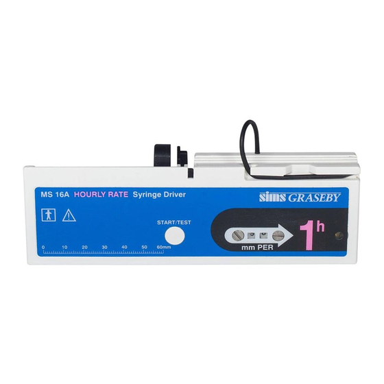
M S 1 6 A S y r i n g e D r i v e r S m i t h s M e d i c a l Chapter 1 - Product Overview Figure 1-1 MS16A Hourly rate syringe driver Description The MS16A Syringe Driver (Figure 1-1) is a portable, battery- operated device, designed for the continuous infusion of small... -
Page 15: Controls
M S 1 6 A S y r i n g e D r i v e r S m i t h s M e d i c a l The clear plastic lockbox is hinged at the back and features a lock at the front. -
Page 16: Packed Set
M S 1 6 A S y r i n g e D r i v e r S m i t h s M e d i c a l Packed set The MS16A packed set (part number 0105-0504) is supplied with the following items:- MS16A Syringe Driver. -
Page 17: Accessories And Consumables
M S 1 6 A S y r i n g e D r i v e r S m i t h s M e d i c a l Accessories and consumables Item Description Part number 100 cm infusion set PVC line with 25 gauge needle. - Page 18 ® Graseby MS16A Syringe Driver Chapter 2 Specification and Standards...
-
Page 19: Chapter 2 - Specification And Standards
S m i t h s M e d i c a l M S 1 6 A S y r i n g e D r i v e r Chapter 2 - Specification and Standards Type: Syringe driver with motor driven linear actuator, pulsed motion. Internal 9 V alkaline battery power source. -
Page 20: Indicator
M S 1 6 A S y r i n g e D r i v e r S m i t h s M e d i c a l Indicator: Low battery level: 7.0 V to 5.5 V (LED stops flashing) Flash period: 1.05 secs ±... -
Page 21: Standards
Complies with RTCA DO-160D (Operation in a commercial aircraft with controlled pressurised cabin area which maintains cabin pressure at normal cabin environment.) Smiths Medical International Ltd. ref. CIB B1100. Biological evaluation: Complies with EN 30993-1:1994 Biological evaluation of medical devices - Part 1: Guidance on selection of tests. -
Page 22: Disposal
M S 1 6 A S y r i n g e D r i v e r S m i t h s M e d i c a l Disposal When disposing of the driver or its accessories do so in the best way to minimise any negative impact on the environment. -
Page 23: Chapter 3 - Circuit Descriptions
® Graseby MS16A Syringe Driver Chapter 3 Circuit Descriptions... -
Page 24: Logic
M S 1 6 A S y r i n g e D r i ve r S m i t h s M e d i c a l Chapter 3 - Circuit Descriptions Refer to Figures 3-1, MS16A Circuit diagram and 3-2, MS16A Printed circuit board layout. -
Page 25: Primary Guard
M S 1 6 A S y r i n g e D r i v e r S m i t h s M e d i c a l Note: The amount of overrun at each step, though indeterminate, is non-cumulative. -
Page 26: Test Circuit
M S 1 6 A S y r i n g e D r i ve r S m i t h s M e d i c a l Test circuit When the START/TEST button is pressed and held, TR3 is turned on by switch S1 (see Start, page 3 - 1) and the motor circuit completed via switch S2. -
Page 27: Ms16A Circuit Diagram
M S 1 6 A S y r i n g e D r i v e r S m i t h s M e d i c a l Figure 3-1 MS16A Circuit diagram 3 — 6 Issue 6 (February 2005) Technical Ser vice Manual... -
Page 28: Ms16A Printed Circuit Board Layout
M S 1 6 A S y r i n g e D r i ve r S m i t h s M e d i c a l Figure 3-2 MS16A Printed circuit board layout Te c h n i c a l S e r v i c e M a n u a l I s s u e 6 ( February 2 0 0 5 ) 3 —... - Page 29 ® Graseby MS16A Syringe Driver Chapter 4 Disassembly and Assaembly...
-
Page 30: Chapter 4 - Disassembly And Assembly
S m i t h s M e d i c a l M S 1 6 A S y r i n g e D r i v e r Chapter 4 - Disassembly and Assembly General Warnings: Refer all service, repair, testing and calibrations only to suitably qualified technical personnel. -
Page 31: Ms16A Exploded View
M S 1 6 A S y r i n g e D r i v e r S m i t h s M e d i c a l Figure 4-1 MS16A exploded view I s s u e 6 ( F e b r u a r y 2 0 0 5 ) 4 —... -
Page 32: Removal And Dismantling Procedures
S m i t h s M e d i c a l M S 1 6 A S y r i n g e D r i v e r Removal and dismantling procedures 1. Case separation Lay the driver face down on a clean flat surface. Slide off the battery cover (item 27) and if fitted, remove the battery. -
Page 33: Motor And Gearbox Disassembly
M S 1 6 A S y r i n g e D r i v e r S m i t h s M e d i c a l The START/TEST pushbutton, seal and switchplate (items 5, 6 and 7) may remain in the case. -
Page 34: Assembly Procedures
S m i t h s M e d i c a l M S 1 6 A S y r i n g e D r i v e r Assembly procedures Note: Unless otherwise stated, tighten all screws to a torque of 30 - 35 cNm. - Page 35 M S 1 6 A S y r i n g e D r i v e r S m i t h s M e d i c a l iii. Apply a smear of silicone grease (Smiths Medical part number 6835-2006) to the edge of the slotted head screw (items 11 and 12).
-
Page 36: Actuator And Bearing
S m i t h s M e d i c a l M S 1 6 A S y r i n g e D r i v e r Note: The motor case has two pegs on the front face, align the motor so that the pegs do not foul the locating pillar in the case assembly. -
Page 37: Case Assembly
M S 1 6 A S y r i n g e D r i v e r S m i t h s M e d i c a l 5. Case assembly Before the case is re-sealed: ensure that all internal work is complete, seal the case halves using a non-acetic silicone sealant (e.g. - Page 38 S m i t h s M e d i c a l M S 1 6 A S y r i n g e D r i v e r Clean off any excess sealant before it sets. The setting time is as specified for the sealant selected.
-
Page 39: Lockbox
M S 1 6 A S y r i n g e D r i v e r S m i t h s M e d i c a l Lockbox Figure 4-7 Lockbox Installation To install the syringe driver in the lockbox: Unlock and open the box. - Page 40 ® Graseby MS16A Syringe Driver Chapter 5 Service Test Proceedures...
-
Page 41: Service Test Procedures
Vernier calipers 0 - 10 V variable DC supply at up to 50 mA. *Dummy rear case (refer to Smiths Medical Service Dept.) Standard Service Department tools and equipment. * A dummy rear case consists of a rear case that has been cut in half so that only the battery end of the case (with two fixing holes) remains. -
Page 42: Adjustments Potentiometers
M S 1 6 A S y r i n g e D r i v e r S m i t h s M e d i c a l Adjustment potentiometers The adjustment potentiometers VR5 and VR9 are behind the front panel label. -
Page 43: Service Testing
S m i t h s M e d i c a l M S 1 6 A S y r i n g e D r i v e r Service Testing Note: Before starting, separate the cases and fit a dummy rear case. Connect a link from TP2, behind the lefthand square window, to +9 V and another link from TP1, behind the righthand square window to 0 V. - Page 44 M S 1 6 A S y r i n g e D r i v e r S m i t h s M e d i c a l To measure the motor interval time, a conventional scope with a good trigger is required;...
-
Page 45: Volt Thrust Test
S m i t h s M e d i c a l M S 1 6 A S y r i n g e D r i v e r Figure 5-4 Using the cam adjustment tool 2. 9 Volt thrust test Fit the dummy case to the driver. -
Page 46: Guard Test
M S 1 6 A S y r i n g e D r i v e r S m i t h s M e d i c a l Connect to the syringe driver a 9 V DC power supply. Set the rate dials to read 99. -
Page 47: Timer And Feed Rate Tests
S m i t h s M e d i c a l M S 1 6 A S y r i n g e D r i v e r Timer and feed rate tests Place the syringe driver in the Linear Accuracy Rig, part number 0105-0858, place the dti extension rod on the actuator assembly and set the dti to zero. -
Page 48: Sounder Check
M S 1 6 A S y r i n g e D r i v e r S m i t h s M e d i c a l 11. Sounder check Check that whenever power is restored (e.g. battery removed and replaced), an undistorted sound, clearly audible at arms length and lasting 5 - 20 seconds, is produced. - Page 49 S m i t h s M e d i c a l M S 1 6 A S y r i n g e D r i v e r o l l ± ( ± c t i c t i c t i .
-
Page 50: Chapter 6 - Maintenance
® Graseby MS16A Syringe Driver Chapter 6 Maintenance... -
Page 51: Cleaning
Smiths Medical supports this policy, and recommends that the tests and if necessary the adjustments given in Chapters 5 and 6 of this publication should be carried out at regular intervals. -
Page 52: Battery Replacement
M S 1 6 A S y r i n g e D r i v e r S m i t h s M e d i c a l Battery replacement The unit uses an IEC 6LR61 battery (9 V, alkaline, PP3 size), e.g. -
Page 53: Continuous Alarm Conversion
S m i t h s M e d i c a l M S 1 6 A S y r i n g e D r i v e r Continuous alarm conversion If required, the alarm may set to a continuous tone when the syringe stops e.g. -
Page 54: Basic Troubleshooting
M S 1 6 A S y r i n g e D r i v e r S m i t h s M e d i c a l Basic Troubleshooting Basic troubleshooting information on the syringe driver is also given in the Instruction Manual, part number 0105-0549. -
Page 55: Chapter 7 Parts List
® Graseby MS16A Syringe Driver Chapter 7 Parts List... -
Page 56: General Assembly Of The Ms16A
S m i t h s M e d i c a l M S 1 6 A S y r i n g e D r i v e r Chapter 7 - Parts List General assembly of the MS16A Item No. - Page 57 M S 1 6 A S y r i n g e D r i v e r S m i t h s M e d i c a l Figure 7-1 Exploded view of the MS16A Syringe Driver Te c h n i c a l S e r v i c e M a n u a l Issue 6 (February 2 0 0 5 ) 7 —...
- Page 58 S m i t h s M e d i c a l M S 1 6 A S y r i n g e D r i v e r General assembly of the MS16A (continued) Item No. Description Part Number Button seal 0105-0032...
- Page 59 M S 1 6 A S y r i n g e D r i v e r S m i t h s M e d i c a l General assembly of the MS16A (continued) Item No. Description Part Number Instruction label - GMI 0105-0552...
-
Page 60: Ms16A Pcb Assembly
S m i t h s M e d i c a l M S 1 6 A S y r i n g e D r i v e r Service manual 00SM-0105 Not illustrated Cam adjusting tool 0105-0079 Not illustrated Spring test gauge assembly 0105-0083... - Page 61 Smiths Medical Int al Int al International Limit ernational Limit ernational Limited Watford, Herts, UK, WD24 4LG www.smiths-medical.com Part No. 00SM-0105-6 February 2005 Smiths Medical - A part of Smiths Group plc © 2005 Smiths Medical family of companies. All rights reserved.
Need help?
Do you have a question about the Graseby MS16A and is the answer not in the manual?
Questions and answers