Table of Contents
Advertisement
Quick Links
Advertisement
Table of Contents

Subscribe to Our Youtube Channel
Related Manuals for Carotron Elite Pro V3


Summary of Contents for Carotron Elite Pro V3
- Page 1 Elite® Pro V3 Modbus® TCP Ethernet Option Card Instruction Manual C14521-000...
-
Page 2: Table Of Contents
Table of Contents 1. General Description....................... 3 2. Specifications ........................ 4 2.1 Electrical ......................4 2.2 Physical ......................4 3. Installation ........................5 3.1 Physical Installation ..................5 3.2 Wiring Guidelines ..................... 5 4. LED Descriptions......................6 5. Configuration Procedure....................7 6. -
Page 3: General Description
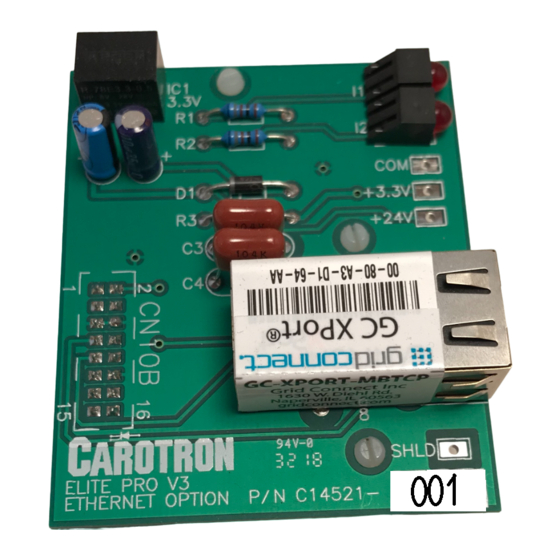
1 1 1 1 General Description Model C14521-000 provides the Elite Pro V3 series of drives with an Ethernet Interface using the Modbus® TCP/IP protocol. The card uses a Lantronix XPort gateway module to translate Ethernet TCP to Modbus® RTU. -
Page 4: Specifications
2 2 2 2 Specifications 2.1 Electrical Power Input Powered internally from Elite Pro V3 drive • Network Interface RJ45 • 10/100M Ethernet • Temperature Range 0-55º C • 2.2 Physical (All dimensions are in inches) Figure 1: Dimensions... -
Page 5: Installation
The C14521-000 option card installs onto the control board of the Elite Pro V3 drive. 1. Remove all power from the Elite Pro V3 drive. This includes main and control power. 2. Align the option card connector CN10B with the control board connector CN10. -
Page 6: Led Descriptions
4 4 4 4 LED Descriptions Module LEDs Right LED State Solid Amber 10BASE-T Solid Green 100BASE-T No Connection Table 1: Connection LED Left LED State Blinking Amber Half Duplex Activity Blinking Green Full Duplex Activity Table 2: Activity LED Option Card LEDs LED I1 State... -
Page 7: Configuration Procedure
Leave the username and password fields blank when prompted. 2. The module's web page configuration utility should be displayed. Below are the standard settings that should be used with an Elite Pro V3 drive. -
Page 8: Figure 2: Server Settings
Figure 2: Server Settings Figure 3: Serial Settings... -
Page 9: Figure 4: Modbus Tcp Settings
Figure 4: Modbus TCP Settings Figure 5: Configurable Pin Settings Note: The Direction selection is irrelevant when the function is set for Status LEDs. -
Page 11: Standard Terms & Conditions Of Sale
1. General charges any such system to so perform, which system is found to the The Standard Terms and Conditions of Sale of Carotron, Inc. (hereinafter Company’s satisfaction to have failed to so perform, or refund to the called “Company”) are set forth as follows in order to give the Company Purchaser the purchase price paid by the Purchaser to the Company in and the Purchaser a clear understanding thereof. - Page 12 3204 Rocky River Road Heath Springs, SC 29058 Phone: 803.286.8614 Fax: 803.286.6063 Email: saleserv@carotron.com Web: www.carotron.com MAN1063-01 Rev. A Issued 10-03-2018...
Need help?
Do you have a question about the Elite Pro V3 and is the answer not in the manual?
Questions and answers