Table of Contents
Advertisement
Quick Links
• 取扱説明書(以下、本書といいます)の『製品使用上のご注意』の内容をよく理解し、本書をよく読んでか
ら操作してください。
Please understand well the contents of "Cautions on Product Use" of Instruction Manual
(hereinafter referred to as "this manual"), and operate it after often reading this manual.
• 本書はいつでも使用できるよう、大切に保管してください。
Please keep this manual carefully to be able to use it at any time.
チコーエアーテック株式会社
CHIKO AIRTEC CO., LTD.
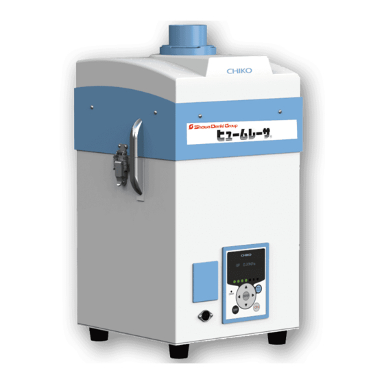
ヒュームコレクタ
Fume Collector
取扱説明書
Instruction Manual
型式/MODELS
CKU-060AT3-ACC
CKU-060AT3-ACC(-T)
CKU-060AT3-ACC(-CE)
051 ( E ) -A
日
本
語
(100V)
(200V)
(220-230V)
Advertisement
Table of Contents

Related Manuals for Showa Denki Chiko CKU-060AT3-ACC


Summary of Contents for Showa Denki Chiko CKU-060AT3-ACC
- Page 1 051 ( E ) -A 日 本 語 ヒュームコレクタ Fume Collector 取扱説明書 Instruction Manual 型式/MODELS CKU-060AT3-ACC (100V) CKU-060AT3-ACC(-T) (200V) CKU-060AT3-ACC(-CE) (220-230V) • 取扱説明書(以下、本書といいます)の『製品使用上のご注意』の内容をよく理解し、本書をよく読んでか ら操作してください。 Please understand well the contents of "Cautions on Product Use" of Instruction Manual (hereinafter referred to as “this manual”), and operate it after often reading this manual. •...
- Page 2 ■はじめに/Introduction このたびは、お買い上げ頂き、誠にありがとうございます。 チコーエアーテック株式会社は「風の技術」を有効に利用し、コンパクトに空気をクリ-ンにすることをテ-マと して努力しております。 この製品は、この風の技術をコンパクトにまとめた省エネ形のクリ-ン BOX です。 長期間故障なく安全にご使用いただくために、この取扱説明書をよくお読みいただき、本機の性能を十分に発 揮できますよう正しいお取扱いをお願いします。 We greatly appreciate that you have purchased our dust collector. CHIKO AIRTEC CO., LTD. is working to achieve clean air with compact equipment while utilizing “air technology” effectively. This machine is an energy-saving-type clean box that realizes “air technology” in a compact body. Please read this instruction manual thoroughly and handle this machine correctly so that you can use it safely for a long time and enjoy its full performance.
-
Page 3: Table Of Contents
Table of contents Chapter 1 Product Usage Precautions ................3 1.1 Safety Notations ..........................3 1.2 Precautions for Transport, Storage, and Relocation ................3 1.3 Precautions for Installation ......................3 1.4 Precautions for Operation ....................... 4 1.5 Other Precautions ........................... 4 1.6 Safety Label Locations ........................ - Page 4 6.3 Removable Flange ..........................27 Chapter 7 Appendix ......................28 7.1 Specifications ..........................28 7.2 Consumables List .......................... 28 7.3 Electrical Diagram ......................... 29 7.3.1 CKU-060AT3-ACC ......................... 29...
-
Page 5: Chapter 1 Product Usage Precautions
Chapter 1 Product Usage Precautions Chapter 1 Product Usage Precautions 1.1 Safety Notations This instruction manual describes usage precautions with the below listed symbols. Be sure to read the instructions. Symbol Meaning Indicates a hazardous situation which, if not avoided, could result in personal death or WARNING serious injury. -
Page 6: Precautions For Operation
Chapter 1 Product Usage Precautions 1.4 Precautions for Operation • Do not suck the following substances: Flammable substances ... Gasoline, thinner, benzine, kerosene, paints, etc. Explosive dusts ... Aluminum, magnesium, titanium, zinc, epoxy, etc. Sparky dust ....Dust containing sparks from high-speed cutting machine, grinder, welding machine, etc. -
Page 7: Safety Label Locations
Chapter 1 Product Usage Precautions 1.6 Safety Label Locations High voltage warning label “Do not disassemble” label Nameplate High voltage warning “Do not disassemble” label Nameplate label CMN011-006 原本 (Original instructions) -
Page 8: Chapter 2 Components Identification
Chapter 2 Components Identification Chapter 2 Components Identification 2.1 Accessories ① ② ③ ④ 100V version 200V version(-T version) 220-230V version(-CE version) ⑤ ⑥ Name Function Qty. Primary filter Collects/adsorbs dust. ① Removes odors by trapping fine particles through collision with Secondary filter ②... -
Page 9: Device Body
Chapter 2 Components Identification 2.2 Device Body 2.2.1 CKU-060AT3-ACC ① ② ③ ⑦ ⑤ ⑥ ④ Name Function Suction port Connects a suction duct. ① (Removable flange) Contains the primary filter, the secondary filter and Suction-side filter case ② the tertiary filters. AT3 panel (operation panel) Operates the device. -
Page 10: At3 Panel
Chapter 2 Components Identification 2.3 AT3 Panel ① ② ③ ④ ⑨ ⑤ ⑤ ⑧ ③ ⑥ ⑦ Name Function Organic EL Displays the operating status and various settings. ① (OLED) display Displays an error or warning number in case of an error or warning. Suction power Green lamps indicate a suction power level (1 to 7). -
Page 11: Display Indications
Chapter 2 Components Identification 2.4 Display Indications 2.4.1 About Modes Normal mode Main power During page 14 MODE SELECT button switch ON stoppage OFF button Page 13 OFF button ON button Held down for 3 sec During Page 13 ENTER button operation Held down for 3 sec 2.4.2 Indications During Stoppage... -
Page 12: Indications During Operation
Chapter 2 Components Identification 2.4.3 Indications During Operation The Up/Down arrow buttons cycle through indications. **.**kPa External pressure **.**kPa Suction pressure **.**kPa Differential pressure **.**kPa Exhaust pressure Blower ***.*°C Temperature around blower Motor rotational frequency Motor *****rpm Indicates the rotational frequency of the currently running motor. Accumulated run time (resettable) Runtime ******h... -
Page 13: Chapter 3 Operation
Chapter 3 Operation Chapter 3 Operation 3.1 Start-up Preparation 3.1.1 Installation ■ Installation location To ensure operating safety and deliver the full performance of the device, install the device in a location that meets the following conditions: Item Description Ambient temperature 0°... -
Page 14: Wiring And Piping
Chapter 3 Operation 3.1.2 Wiring and Piping ■ Wiring • Perform wiring firmly, without bending or pulling cables with excessive force. Fire or electric shock may result. WARNING • Ensure that the power supply conforms to the specifications of the device. •... -
Page 15: Registering Initial Pressures
Chapter 3 Operation 3.3 Registering Initial Pressures Air volume reduction due to filter clogging is judged based on a registered initial differential pressure and indicated as low air volume (WARN4). Register initial pressures through these steps: Perform the wiring and piping of the device. Start the device at a desired suction power level. -
Page 16: Chapter 4 Configuring Settings (Mode Select Mode)
Chapter 4 Configuring Settings (MODE SELECT Mode) Chapter 4 Configuring Settings (MODE SELECT Mode) 4.1 Screen Transitions in MODE SELECT Mode To move to the MODE SELECT mode, press the button during stoppage. MODE SELECT cycle through parameters. Up/Down arrow buttons Communication format setting mode [Com Setting] (... -
Page 17: Air Volume-Down Alert Timing Setting Mode
Chapter 4 Configuring Settings (MODE SELECT Mode) Press the ENTER button to determine the setting. To exit this mode, press the button to return to normal mode. MODE SELECT 4.3 Air Volume-Down Alert Timing Setting Mode This mode allows for changing the timing for displaying an ) as desired. -
Page 18: Accumulated Run Time Reset Mode
Chapter 4 Configuring Settings (MODE SELECT Mode) The date setting screen appears. Press the arrow buttons to change the value. Up/Down Press the button to determine the value. ENTER Set the value in this order: year, month, and day. After the date is set, the time setting screen appears. Press the arrow buttons to change the value. -
Page 19: Chapter 5 Maintenance And Checkup
Chapter 5 Maintenance and Checkup Chapter 5 Maintenance and Checkup • Before starting maintenance and checkup, be sure to break the electrical CAUTION circuit by turning off the power supply and disconnecting the plug from the power outlet. 5.1 Replacing Filters If clogging occurs, a “... -
Page 20: Replacing The Secondary Filter
Chapter 5 Maintenance and Checkup 5.1.2 Replacing the secondary filter 5.1.1 「 Replacing the Primary filter 」 Secondary filter (Page 17) Maintenance Grasp the handle and replace the activated carbon box. The handle is reused. * The new activated carbon box does not come with a handle. -
Page 21: Replacing Fuse
Chapter 5 Maintenance and Checkup 5.2 Replacing Fuse Replace the fuse if any of them is blown by an overcurrent due to trouble with internal equipment. The fuse is contained in the black box beside the power switch. The replacing fuse should be designated by CHIKO AIRTEC Designated fuse: 218 Series from Littell fuse [250V 5A]... -
Page 22: Replacing The Button Battery
Chapter 5 Maintenance and Checkup 5.3 Replacing the Button Battery • The button battery case used in the device is for size. CR2477 Do not use button batteries other than CR2477 CAUTION • Turn on the electricity of the device while replacing the battery, or it will cause a huge consumption of the battery. -
Page 23: Errors/Warnings
Chapter 5 Maintenance and Checkup 5.5 Errors/Warnings If an error/warning occurs, the self-diagnosis function built-in the device lights (flashes) the lamp ERROR and shows display data and error number alternately on the display. For a description of errors/warnings displayed, see “5.5.2 Error/Warning Table”... -
Page 24: Error/Warning Table
Chapter 5 Maintenance and Checkup 5.5.2 Error/Warning Table ERROR Device Error No. Description Action Error/warning Priority lamp operation Follow the remedies for ② in Rotational Motor rotational High Remains ERR03 frequency frequency declining (or Flashing “5.6 Troubleshooting” operational error stopping) Page 23). -
Page 25: Troubleshooting
Chapter 5 Maintenance and Checkup 5.6 Troubleshooting Trouble phenomenon Cause Remedy Power not turned on. Turn on the power. Organic display ① Replace the fuses. shows nothing. Blown fuse “5.2 Replacing Fuse” (page 19) Call for repair. Faulty motor The motor must be replaced. [1] Check that the exhaust/suction ports are not blocked. -
Page 26: Chapter 6 Useful Utilization (Optional)
Chapter 6 Useful Utilization (Optional) Chapter 6 Useful Utilization (Optional) 6.1 Remote Cable 6.1.1 Electrical Diagram Operation input signal Remote operation change signal Operating pressure signal 1 to 5 Vdc Filter clogging signal Dielectric withstanding voltage Operation signal is up to 50 VDC. Also, use the inductor with a current of less than 100mA. - Page 27 Chapter 6 Useful Utilization (Optional) ■ Connection examples ● Pins ① and ④ (input) Device side Customer side Do not apply Pin ① or ④ voltage. Pin ⑧ Reference circuit ● Pin ② (analog output) Device side Customer side Output voltage: 1 to 5 V 0.2 V Measuring instrument, etc.
-
Page 28: Pin Assignments
Chapter 6 Useful Utilization (Optional) 6.1.2 Pin Assignments Wire color Pin # Signal name Description Operation input With ④ and ⑧ short-circuited, ① is short- Black ① signal circuited to start operation. ④ and ⑧ are short-circuited to start remote Remote operation operation. -
Page 29: Remote Operation
Chapter 6 Useful Utilization (Optional) 6.1.3 Remote Operation • For on/off switching via remote operation, short-circuit pins ④ and ⑧. Pin ① is short-circuited ON Pin ① is not short-circuited OFF “6.1.2 Pin Assignments” (page 26). • Do not short-circuit between pins ④ and ⑧ when taking signals by on/off switching on the device side. -
Page 30: Chapter 7 Appendix
Chapter 7 Appendix Chapter 7 Appendix 7.1 Specifications Max. Motor rated Current Frequen Noise Max. suction Model Voltage suction Mass static pressure output value value* volume 100 V* CKU-060AT3-ACC 2.3 A single phase 200 V 50/60Hz 2.8m /min 2.5kPa 53 to 61 dB 15.8kg CKU-060AT3-ACC-T 1.5 A... -
Page 31: Electrical Diagram
Chapter 7 Appendix 7.3 Electrical Diagram 7.3.1 CKU-060AT3-ACC For illustration purpose, these boards are viewed with the opposite sides seen through. CMN011-006 原本 (Original instructions) - Page 32 ■ Scope of Warranty and Responsibility ● Warranty period We will repair free of charge any failures or damages that may occur during normal operating conditions within 12 months of shipment. However, this does not apply to the consumables listed in “7.2 Consumables List”.
- Page 33 販売元/Distributor ※支店・営業所・製造拠点の最新情報は、弊社ホームページよりご確認下さい。 For the latest information on our branches, sales offices, and factories, please visit our website. https://www.showadenki.co.jp 製造元/Manufacturer チコーエアーテック株式会社 CHIKO AIRTEC CO.,LTD. 〒562-0012 大阪府箕面市白島 2-27-24 2-27-24,Hakushima, Minoh, Osaka 562-0012, Japan TEL (81) 072-720-5151 FAX (81) 072-720-5133 URL http://chiko-airtec.jp/...
Need help?
Do you have a question about the Chiko CKU-060AT3-ACC and is the answer not in the manual?
Questions and answers