
Related Manuals for Radionode RN400-T2CS

Summary of Contents for Radionode RN400-T2CS
- Page 1 IoT 4~20mA Signal Data Logger RN400-T2CS User Manual 2021 | Rev. 1 Keep this document nearby so that it may be referred to when needed.
-
Page 2: Table Of Contents
CONTENTS About this Manual Intellectual Property Rights Notational Conventions Introduction Key Features Exterior Accessories Specifications Installation Terminal Block Data Logger Installation Connecting Terminal Block 4-20mA Signal Sensor Operation Viewing Channel Information Viewing Device Information Resetting Data Logger Memory Card for Data Logging Configuration Device Information Server... - Page 3 RS-485 Modbus Communication Tapaculo 365 Adding Devices from Your Smartphone Adding Devices from Your Computer Maintenance Cleaning Batteries Firmware Update Customer Service Information Manufacturer Contact Information Warranty Limit of Liability Certifications HTTP Radionode Protocol V2 Check-in Data-in Order List Data Logger Accessories...
-
Page 4: About This Manual
About This document contains instructions for usage and installation of the RADIONODE RN400-T2PS. Product specifications and certain ® this features herein may be subject to change without prior notice. Figures used in this manual are for explanatory purposes only, and Manual may differ from your system depending on installation conditions. -
Page 5: Introduction
Introduction The RADIONODE RN400-T2PS Data Logger periodically measures temperature and RH, then sends measurement data to the Tapaculo ® 365 server. The RN400-T2PS has a total of 4 I/O channels. External 4~20mA External 4~20mA Channel 1 Channel 2 Analog Sensor... -
Page 6: Exterior
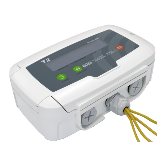
Exterior POWER ON/OFF ❶ ❷ ❸ Display Menu button Display button ❹ ❺ Power button Cable gland Power cables and cables of other devices, such as external sensors, are connected via cable glands to the internal terminal block. For instructions on how to use the buttons, see Operation on page... -
Page 7: Accessories
DC Adapter (12 V, 500 mA) In the event of power failure, two C-type 1.5 V batteries or one 3.6 V battery must be placed in the Data Logger. RADIONODE Data Logger is designed to not operate without a battery, even when external power is connected. -
Page 8: Specifications
Specifications RN400-T2PS Data Logger Ch1 : 4 ~ 20mA Analog (accuracy: ±0.8 F.S.) Ch2 : 4 ~ 20mA Analog (accuracy: ±0.8 F.S.) External Sensor Ch3 : 4 ~ 20mA Analog (accuracy: ±0.8 F.S.) Ch4 : 4 ~ 20mA Analog (accuracy: ±0.8 F.S.) 2.4 GHz IEEE 802.11 b/g/n WPA2-Enterprise Communication... -
Page 9: Installation
Installation The following procedure will guide from the installation procedure to the Tapaculo 365 registration process. Install sensors or connect other devices to the Data Logger as needed. Connect power and insert the battery. Use the virtual Wi-Fi router feature to configure the Data Logger. Configuration on page Now that the Data Logger has been installed, it must be registered... -
Page 10: Terminal Block
Terminal Terminal Blocks can be found inside of a Data Logger, with other components arranged as follows: Block ❶ ❷ ❸ Micro SD Card Slot Battery Holder OLED Connection ❹ ❺ ❻ FPC/FFC Connection USB for 4~20mA Input Calibration ❾ Select Battery ❽... -
Page 11: Data Logger Installation
Data Logger The general procedure for installing a Data Logger is as follows: Installation Loosen the screw on the right side of the front panel and open the front panel. Loosen the cable gland. Route the cables of the device that will be connected through the gland and connect to the terminal block. - Page 12 Tighten the gland firmly. Cover the front panel and tighten the screws. There Data Logger is equipped with a magnet at the rear. Place the Data Logger on a steel panel. If necessary, use screws to secure. There are three screw holes on the back of the device.
-
Page 13: Connecting Terminal Block
Connecting Terminal Block When connecting cables to the terminal block, ensure that the flat cable does not get disconnected from the front connector. Cable Gland If Data Logger cable gland cannot sufficiently receive all cables, install additional cable glands. There are two more gland slots at the bottom of the Data Logger. -
Page 14: 4-20Ma Signal Sensor
4-20mA Signal Sensor Sensor For using loop power, connect the 4~20mA signal with DC power supply so that the current can flow from + to - on the input terminals Connection as shown above. No additional resistor connection is required at this time. - Page 15 PC Connection Refer to the figure above when you connect to your PC for calibration. 4-20mA 4-20mA 4-20mA 4-20mA INPUT INPUT INPUT INPUT POWER RS485 5~30V Setting Scaler from UA-CALIBRATOR Select 3. USB CALIBRATION from RN400 device menu. Connect RN400 to PC with Micro USB. Run UA-CALIBRATOR Ver 5.8 or higher software on PC.
- Page 16 How to set up the scale Select a sensor. Each RN400-T2CS can active Maximum 4 CH of sensor. Select the type of signal and click the save button. ・ 4-20mA ・...
- Page 17 How to do error-correction on UA-Calibrator(Zero/Span) If the reading value has a fine error, calibration procedure would be required with UA-Calibrator. In some cases, 4.00mA sensor value shows as 3.95mA, then press CALIBRATION WIZARD button to re- calibrate. Calibration Wizard can precisely adjust small differences of sensor’s output.
- Page 18 Batteries Insert two C-type 1.5 V batteries into the battery holder, or one 3.6 V battery into the left-hand battery holder. Be careful not to connect batteries with opposite polarities. Doing so may damage the device. If you are using a 3.6 V battery, move the BAT jumper to the B position.
-
Page 19: Operation
Operation When the data logger is turned on, the model number and other key information is displayed with the corresponding measurements. If no external power is supplied, the display will turn off shortly and the Data Logger will enter sleep mode. POWER ON/OFF Viewing Channel Information: To view channel information,... -
Page 20: Viewing Channel Information
Viewing Press the button repeatedly to display the below channel data. A sensor channel that is not connected will appear as (none) (none). Channel Measurements of Channels Information LAST SENSING |S:menu LAST SENSING |S:menu 1 and 2 1: 26.2C |2: 21.6% 1: 26.2C |2: 21.6% Measurements of Channels LAST SENSING |S:menu... -
Page 21: Viewing Device Information
Viewing To view device information, select 1.VIEW INFO 1.VIEW INFO. To view the next item, press the button. To exit, press the button. Device Number of datasets to send Information INFO|S:next, P:exit INFO|S:next, P:exit to the server in the next 1.HOLDING DATA: 4 1.HOLDING DATA: 4 cycle. -
Page 22: Resetting Data Logger
DNS server IP address INFO|S:next, P:exit INFO|S:next, P:exit 9.DN:210.220.163.82 9.DN:210.220.163.82 Data Logger MAC address INFO|S:next, P:exit INFO|S:next, P:exit 10.MAC:508CB16FA1B3 10.MAC:508CB16FA1B3 Firmware version INFO|S:next, P:exit INFO|S:next, P:exit 11.SW BUILD:20200720 11.SW BUILD:20200720 Model No. INFO|S:next, P:exit INFO|S:next, P:exit 12.MODEL:RN400T2PS 12.MODEL:RN400T2PS Alarm relay status INFO|S:next, P:exit INFO|S:next, P:exit 13.ALARM:OFF (BAT.) -
Page 23: Memory Card For Data Logging
Memory If a memory card is installed in the Data Logger, measurement data will be written to the memory card as a CSV file as follows: Card for Data Measurement date, timestamp, Mac address, value for Logging Channel 1, ... , value for Channel 4 In the temp channel (Ch. -
Page 24: Configuration
Configuration The Data Logger is equipped with a virtual Wi-Fi router. The virtual router allows your smartphone or tablet to be linked to Data Logger for configuration. Select 2.CONFIG MODE(AP) to enable the virtual router. Select 2.CONFIG MODE(AP) The following will appear in the display: SOFTAP: _RN400-A1B3 SOFTAP: _RN400-A1B3 ACCESS: 192.168.1.1... - Page 25 Open your smartphone’s web browser and type "192.168.1.1" "192.168.1.1" in the address bar. The Settings page wiill appear. Change the settings on each page, then tap Save. To finish configuration, tap Reboot.
-
Page 26: Device Information
Device Tap SYSTEM to view Data Logger device information. Information Tapaculo365 Owner Tapaculo 365 account ID Mac ADDRESS Data Logger MAC address Model Name Data Logger model number Firmware version Firmware version OTA Release Version OTA Release Version If a memory card is not inserted, No SDCard SDCARD Inserted will appear. -
Page 27: Server
Datain URL data-in requests. For check-in and data-in request formats, see HTTP Radionode Protocol V2 on page This item will appear if Destination is set to SDCard Logger. If set to "0", measurement data will begin to be written to the memory card as soon as booting completes. -
Page 28: Measurement
Measurement Tap MEASUREMENT to configure sensor operation. S e l e c t t h e i n t e r v a l b e t w e e n s e n s o r measurement and data transmission. For instance, if Sensing 1Min - Sending 5Min is Sensing - Sending selected, sensor measures every 1 minute,... - Page 29 Adjusts the sensor sensitivity. The margin AVG Filter of error ranges from 1 to 15, and the higher the value, the lower the sensitivity. CH info Displays a list of I/O channels. Select the input channel that will trigger the alarm relay and specify the normal range.
-
Page 30: Wi-Fi Network
Wi-Fi Tap WIFI/NETWORK SETUP to configure the Wi-Fi network that will be used by the Data Logger. Network Select a network to use from the list of searched Wi-Fi networks. The closer the Access Point signal strength is to 0 dBM, the stronger the connection. - Page 31 If a static IP address is needed, select Static and configure additional settings as follows: Data Logger IP Address Gateway Gateway IP address Subnet Subnet mask DNS server IP address...
- Page 32 Enterprise When connecting to a Wi-Fi network that uses enterprise security, the certificate is passed from Data Logger to the RADIUS server Security (WPA along with the RADIUS server account. Once user’s access is Enterprise) authorized by the RADIUS server, access to the network is granted. To connect to a network that uses enterprise security, adhere to the following procedure: Copy the RADIUS server certificate to a micro SD card with the...
-
Page 33: Display
Display Tap DISPLAY/OTHERS to configure display and other options. This setting can be configured with other settings to set the display operation interval D i s p l a y T i m e r O P during sleep mode. Select how long the Mode display will stay on in minutes. -
Page 34: Memory Card Usage Configuration
Memory Memory cards facilitate the configuration of multiple Data Loggers at once. Card Usage Configuration Back up the setup data on a memory card in the configured Data Logger. a) Insert a micro SD card into the Data Logger. b) On the DISPLAY/OTHERS page, tap Copy to SD Card > Copy Now. -
Page 35: Checking Communication With Tapaculo 365 Server
RS-485 Modbus The UA Calibarator program is required to change settings of Modbus RTU communication. Download and install UA Calibarator Communication from the RadioNode web site at www.radionode365.com www.radionode365.com . From the Data Logger, select 3.USB CALIBRATION 3.USB CALIBRATION. Connect the Data Logger to your computer using a USB cable. -
Page 36: Tapaculo 365
Tapaculo 365 is a cloud-based sensor monitoring web application ® operated by DEKIST, a radionode manufacturer. We offer data storage for all sensor-measured data, and provide various features such as emergency alarms, reports, and real-time status based on stored data. -
Page 37: Adding Devices From Your Smartphone
Adding At the New Device page, you will find a unique QR code for your account. The QR code allows you to easily add devices and channels Devices to your smartphone. from Your Smartphone Scan the QR code with your smartphone. Alternatively, copy the link address from the QR code image and send it to your smartphone. - Page 38 Enter the i-code on the device display. If you do not see an i-code on the display, tap Search by MAC address and enter your MAC address. If the i-code or MAC address is correct, the device information will appear as below. Tap Next.
- Page 39 Enter your device name, check the box of the channel that will be used, then enter the channel name and unit that will be used. Tap Next to finish.
-
Page 40: Adding Devices From Your Computer
Adding The New Device page will appear if there is no added device on login. To add a device that was added later, click Device Setup > New Devices Device. from Your Computer Adding Devices Devices found in the same IP band are listed here. If you do not see your device in the list, you can add it using its i-code. - Page 41 Adding Once your device has been added, click Device Setup > New Data Channel. All added device channels will be listed. Channels This list also includes channels not associated with external sensors or other devices. Adding a channel essentially means selecting a channel to monitor.
- Page 42 Adding Widgets A widget contains one or several channels. You can add a widget to the dashboard by clicking Dashboard, then Add widget. Enter the widget name in the window, select channels, then click Save.
-
Page 43: Maintenance
Maintenance Cleaning Use a dry cloth to clean the Data Logger. Do not use solvents or abrasives. Not only do these substances damage the surface of the Data Logger, but they may also affect sensor performance. Batteries Replace the battery when the battery status on the Tapaculo 365 web page is Bad, or if it appears as follows: WARNING! |S:menu WARNING! |S:menu... -
Page 44: Firmware Update
Firmware The Data Logger can be updated with new firmware to correct errors or enhance features. Latest firmware is distributed optionally Update depending on your circumstances. Copy the firmware file to a micro SD card to the following path and insert it into Data Logger. The file name is the same as the model number. -
Page 45: Customer Service Information
Customer Service Information Manufacturer DEKIST Co., Ltd. provides repair service and replacement parts for RADIONODE products. To request customer service, contact us via Contact one of the following methods. Information Tel: +(82) 1566-4359 ● Fax: (+82) 31-8039-4400 ● E-mail: master@dekist.com ●... -
Page 46: Certifications
Certifications This equipment has been tested and found to comply with the limits for a Class A digital device, pursuant to part 15 of the FCC Rules. These limits are designed to provide reasonable protection FCC Class A against harmful interference when the equipment is operated in a commercial environment. -
Page 47: Http Radionode Protocol V2
HTTP Radionode Protocol V2 Radionode users can build their own servers that receive measurement data from radio node devices, such as the RN400 Series data loggers or RN17x Series data transmitters, instead of the Tapaculo 365. This chapter describes the POST-method HTTP request format used by radionode devices for customer server developers. - Page 48 In 192.168.10.1/checkin 192.168.10.1/checkin , checkin checkin is the server program name that processes check-in requests, which can be either checkin. checkin. php, checkin.asp php, checkin.asp or checkin.js checkin.js . mac : MAC address of the device ● ver : Firmware version ●...
- Page 49 The first two of the five tags are mandatory, whereas the remaining three tags are options, subject to change according to the server's reply. ack : Processing outcome ( ok ok or error error ) ● timestamp timestamp : Current time of the server in UNIX timestamp ●...
-
Page 50: Data-In
Data-in Data-in requests are in the following format: POST / HTTP/1.1 POST / HTTP/1.1 Host: 192.168.10.1/datain Host: 192.168.10.1/datain Content-Type: application/x-www-form-urlencoded Content-Type: application/x-www-form-urlencoded Content-Length: 589 Content-Length: 589 mac=0000xxxx0000& mac=0000xxxx0000& sig=40& sig=40& bat=255& bat=255& volt=1|3.12& volt=1|3.12& SMODEL=RN400H2EX& SMODEL=RN400H2EX& C000=1505912142|23.22|12.44|122.11|123& C000=1505912142|23.22|12.44|122.11|123& P000=1505911542|23.19|12.40|121.96|123& P000=1505911542|23.19|12.40|121.96|123& P001=1505910942|23.18|12.52|122.04|123&... -
Page 51: Order List
Temp, RH, PR-P1-3, PR-P1-15, PR-K1-3, PR-K1-15 RN400-H2EX Door AP-D1, AP-W1 Temp RN400-T2PS PR-N1-20, PR-N1-150, RG20 Temp, PR-P1-3, PR-P1-15, PR-K1-3, PR-K1-15 RN400-T2EX PR-T1-3, PR-T1-15, AP-D1, AP-W1 Door Temp RN400-T2TS PR-K1-3, PR-K1-15 PR-T1-3, PR-T1-15 4-20mA RN400-T2CS RN400-T2GS RG10-NH3, RG10-H2S PM2.5 RN400-T2PM Particulate matter... -
Page 52: Accessories
Accessories Temp Sensor Type Model No. Cable PT100 PR-P1-3 PT100 PR-P1-15 15 m Type K Thermocouple (TC-K) PR-K1-3 Type K Thermocouple (TC-K) PR-K1-15 15 m Type T Thermocouple (TC-T) PR-T1-3 Type T Thermocouple (TC-T) PR-T1-15 15 m PR-N1-20 20 cm PR-N1-150 150 cm Temp &... - Page 53 ⓒ 2021 DEKIST Co., Ltd. Telephone 1566-4359 Fax (+82) 31-8039-4400 Email master@dekist.com #A1801, 13, Heungdeok 1-ro, Giheung-gu, Yongin-si, Gyeonggi-do, Korea 16954...
Need help?
Do you have a question about the RN400-T2CS and is the answer not in the manual?
Questions and answers