Table of Contents
Advertisement
Quick Links
Advertisement
Table of Contents

Related Manuals for Powermatic DT65


Summary of Contents for Powermatic DT65
- Page 1 This .pdf document is bookmarked Operating Instructions and Parts Manual Single End Dovetailer Model DT65 Powermatic 427 New Sanford Road LaVergne, Tennessee 37086 Part No. M-1791305 Ph.: 800-274-6848 Revision B 02/2016 www.powermatic.com Copyright © 2014 Powermatic...
-
Page 2: Warranty And Service
Warranty and Service Powermatic warrants every product it sells against manufacturers’ defects. If one of our tools needs service or repair, please contact Technical Service by calling 1-800-274-6846, 8AM to 5PM CST, Monday through Friday. Warranty Period The general warranty lasts for the time period specified in the literature included with your product or on the official Powermatic branded website. -
Page 3: Table Of Contents
Warning ..............................4 Introduction ............................. 6 Description .............................. 6 Specifications ............................6 Features of the DT65 Dovetailer ......................7 Terminology ............................7 Unpacking ............................... 8 Contents of the Shipping Container ...................... 8 ... -
Page 4: Warning
5. Do not use this dovetailer for other than its intended use. If used for other purposes, Powermatic disclaims any real or implied warranty and holds itself harmless from any injury that may result from that use. - Page 5 21. Give your work undivided attention. Looking around, carrying on a conversation and “horse-play” are careless acts that can result in serious injury. 22. Maintain a balanced stance at all times so that you do not fall or lean against the cutter or other moving parts.
-
Page 6: Introduction
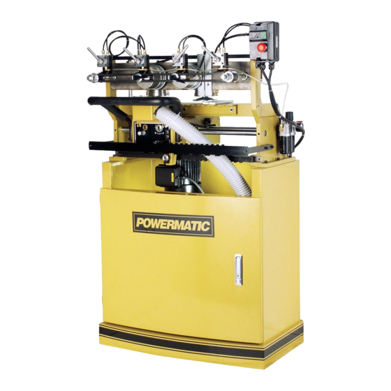
Powermatic. Powermatic can also be reached at our web site: www.powermatic.com. Description The Model DT65 Dovetailer will make cleanly cut half-blind dovetails for drawer or box construction. A four-sided template allows any of four pitches, from 1” up to 2-1/2”. The use of different dovetail pitches will give a unique custom appearance to your work. -
Page 7: Features Of The Dt65 Dovetailer
Features of the DT65 Dovetailer Terminology Below are the terms used in this manual to identify types of cuts and measurements. -
Page 8: Unpacking
Contents of the Shipping Container Unpacking Dovetail Machine Open shipping container and check for shipping Fixed Chasers (2-1/2” and 3” pitches) damage. Report any damage immediately to Indication Template your distributor and shipping agent. Do not Set of Open-Ended Wrenches (8-10, 11-13, discard any shipping material until the Dovetailer 12-14, and 17-19mm) is assembled and running properly. -
Page 9: Installation & Assembly
Installation & Assembly Tools required for assembly forklift or hoist with straps/slings 14mm wrench (provided) [NOTE: A socket set with ratchet wrench may speed assembly] 4mm hex wrench (provided) knife or wire cutter flat head screwdriver Remove the four screws and flat washers Figure 1 holding the machine to the pallet with a 14mm wrench, as shown in Figure 1. -
Page 10: Installing Dust Chute
Connect the intake hose of your dust collector to the 4” diameter dust chute at the back of the cabinet (Figure 5). NOTE: A variety of dust collection systems are available from Powermatic. Call customer service at 1-800-274-6848 or visit our website for more information. -
Page 11: 230 Volt Operation
230 Volt Operation As received from the factory, the DT65 Dovetailer is designed to run on 230 volt power only. You may either connect a UL/CSA listed 230V plug (similiar to the one shown in Figure 6) or “hard-wire” the machine directly to a control panel. -
Page 12: Adjustments
Adjustments Disconnect machine from power source, shut off air supply and bleed residual air from system, before making adjustments. Failure to comply may cause serious injury. Clamping Cylinders The workpieces are clamped to the table by pneumatically operated aluminum cylinders (A, Figure 9). -
Page 13: Clamping Pressure
The clamping cylinders can also be adjusted laterally for better support of workpieces with differing widths. Simply loosen the locking handle (Figure 11) and slide the clamping cylinder to position. Re-tighten locking handle. Clamping Pressure The pressure exerted by the cylinder clamps against the workpiece can be adjusted at the air regulator, shown in Figure 12. -
Page 14: Indication Template
The spacing between the “fingers” of the fixed chaser allows clearance for the cutter. The DT65 Dovetailer comes standard with three fixed chasers at 2”, 2-1/2” and 3” pitches. (Pitch is the distance between the centers of the “fingers”;... -
Page 15: Horizontal And Vertical Fences
1. To replace the fixed chaser, remove the three M6 socket head cap screws and flat washers, using a 5mm hex wrench as shown in Figure 17. Remove the fixed chaser. 2. Install the new fixed chaser and make sure it is level with the main table. - Page 16 NOTE: Make sure locking handles (A & B, Figure 19) will not interfere with the headstock during operation. 5. Continue to check the spacing by sliding the headstock across, until the dovetail cuts will be distributed evenly across the width of the workpiece.
-
Page 17: Buffer Pads
There are a total of four fences on the DT65 Dovetailer – two vertical and two horizontal. These allow two sets of workpieces to be cut at the same time. If this is desired, position the other two fences in the same manner as the first two fences, remembering again to offset the vertical fence by half the pitch. -
Page 18: Thickness Of Tenon Cut
3. To decrease the depth of the mortise (female) cut, turn the bolt clockwise. To increase the depth of the mortise cut, turn the bolt counterclockwise. 4. Re-tighten the hex nut. Thickness of Tenon Cut To adjust the thickness of the tenon (male) cuts, you will change the depth of the tracer pin (A, Figure 24). -
Page 19: Drive Belt Tension
NOTE: One notch of the scale equals 1mm. 6. With your fingers on the shank portion of the cutter, carefully rotate the cutter toward the plus (+) or minus (-) position as needed. 7. When satisfied with the adjustment, tighten both set screws firmly. -
Page 20: Operation
Operation NOTE: The following are basic dovetailing procedures as they apply to this machine, and are not intended to be a full course of instruction in making dovetails. Refer back to the terminology on page 7 if needed. The Dovetailer can be used to make joints in drawers, boxes, cabinets, etc. - Page 21 5. Activate the clamping cylinder in front of the RIGHT SIDE workpiece. 6. Place the drawer BACK on the horizontal table, and against the horizontal fence. Slide it flush against the RIGHT SIDE workpiece. The bottom groove on the BACK should face downward and opposite the fence.
-
Page 22: Preventing Chip Out
Preventing Chip Out As noted previously, when the SIDE and FRONT/BACK pieces are inserted into the machine, they are offset a bit so they’ll match correctly when assembled. In other words, the SIDE will rest slightly to the right of the FRONT/BACK in the machine. -
Page 23: Maintenance
Keep clean the travel rods upon which the Maintenance headstock slides. Lubrication Before doing maintenance on the machine, disconnect it from the electrical The linear bushings by which the headstock supply and the air supply, and release any travels on the rods are pre-lubricated and residual air from the lines. - Page 24 Troubleshooting the DT65 Dovetailer Trouble Probable Cause Remedy Machine will not Machine not plugged in. Verify machine is connected to power start/restart or Fuse blown, or circuit repeatedly trips Replace fuse, or reset circuit breaker. breaker tripped. circuit breakers or blows fuses.
- Page 25 Trouble Probable Cause Remedy Cutter in wrong position. Turn cutter towards the (+) or (-) mark [page 18]. Cutter not cutting properly. Cutter dull or damaged. Sharpen or replace cutter [page 19]. Dovetailed parts fit Cutter not adjusted Loosen set screws and turn cutter toward the (+) too tightly.
-
Page 26: Replacement Parts
Replacement parts are listed on the following pages. To order parts or reach our service department, call 1-800-274-6848, Monday through Friday (see our website for business hours, www.powermatic.com). Having the Model Number and Serial Number of your machine available when you call will allow us to serve you quickly and accurately. -
Page 27: Base Assembly
Base Assembly... -
Page 28: Parts List: Hold-Down Assembly
Index No. Part No. Description Size 1 ....DT65-301 ....Cylinder Assembly (Index #2 thru #16) ..........4 2 ....DT65-302 ....Cylinder Body ..................4 3 ....DT65-303 ....Piston ....................4 4 ....DT65-304 ....Wearing ....................4 5 .... -
Page 29: Hold-Down Assembly
Hold-Down Assembly... -
Page 30: Parts List: Headstock Assembly
20 ..... TS-1550071 .....Flat Washer ............M10 ......1 21 ..... TS-1540071 .....Hex Nut ..............M10 ......1 22 ..... DT65-222 ....Hex Head Bolt ............M10x150 ....1 23 ..... DT65-223 ....Indication Bracket .................. 1 24 ..... TS-1550031 .....Flat Washer ............M5 ......6 25 ..... - Page 31 Index No. Part No. Description Size 58 ..... DT65-258 ....Dust Hood ..................... 1 59 ..... DT45-255 ....Window ....................1 60 ..... TS-2171012 .....Machine Screw ...........M4x6 ......4 61 ..... DT45-257 ....Cutter ....................1 62 ..... TS-1502031 .....Socket Head Cap Screw ........M5x12 ......2...
-
Page 32: Headstock Assembly
Headstock Assembly... -
Page 33: Parts List: Cabinet Assembly
5 ....TS-1504061 .....Socket Head Cap Screw ........M8x30 ......6 6 ....TS-1524021 .....Socket Set Screw ..........M8x10 ......6 7 ....DT65-407 ....Flexible Hose............2-1/2” ......1 8 ....DT45-308 ....Hose Clamp ............2-1/2” ......2 9 ....DT45-309 ....Eye Bolt ..............M10 ......2 10 ..... -
Page 34: Electrical Connections
Electrical Connections... - Page 36 427 New Sanford Road LaVergne, Tennessee 37086 Phone: 800-274-6848 www.powermatic.com...
Need help?
Do you have a question about the DT65 and is the answer not in the manual?
Questions and answers