Table of Contents
Advertisement
Quick Links
Advertisement
Table of Contents

Related Manuals for JNE ALLVIS


Summary of Contents for JNE ALLVIS
- Page 1 ALLVIS MANUAL MEASURING SYSTEM Allvis – Manual (EN 2013-02-21)
-
Page 2: Table Of Contents
1.1 General ............................3 1.2 Maintenance ..........................5 1.3 Liability ............................6 1.4 Warranty............................7 2 Allvis Measuring System ........................8 2.1 General Description ........................8 2.2 Display Functions ........................... 9 2.3 Height Calibration Rods ....................... 11 2.4 Magnetic Attachment........................11 2.5 Datum Height Rods ........................ -
Page 3: Introduction
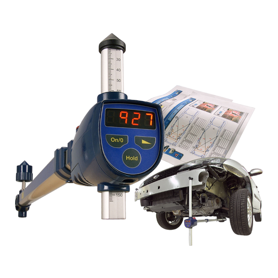
1 Introduction 1.1 General Congratulations on your purchase of the Allvis vehicle measuring system. Allvis is an electronic measurement system intended for measuring and checking dimensional accuracy of vehicle unibody and frame. The system consists of three main components: •... - Page 4 Measurements on Allvis data sheets should be seen as guideline values, since dimensions of vehicles of the same model and year can vary as a result of manufacturing tolerances or previous repairs, also as a result of manufacturer’s subsequent design changes.
-
Page 5: Maintenance
Allvis certified distributors use control instruments provided by JNE AB to accurately perform inspections. D. Scrapping When it becomes necessary to scrap any of the Allvis measuring system equipment or parts it is essential that every item be sorted for recycling in accordance with local, state and federal requirements. -
Page 6: Liability
No part of this publication or Allvis data sheets may be copied in any form, or illegally stored in any computerized system other than the unit covered by the Allvis subscription agreement signed by the purchaser or user as authorized by JNE AB. -
Page 7: Warranty
Allvis equipment is intended for use in the auto body shop environment and in accordance with all recognized and applicable safety rules and regulations. -
Page 8: Allvis Measuring System
Distance measurements from center of the rear calibrated rod holder to center of the front datum height rod holder is generated by electronic impulses produced by a rotating wheel inside the arm. For operating instructions - refer to item numbers 2.2 to 2.10 Allvis – Manual (EN 2021-05-25) -
Page 9: Display Functions
1 mm gradients. Additional comparative checking is possible by repeating the above procedure at any time during comparative checking. To resume normal length measuring i.e. 900-2650 mm settings, simply depress the button < 1 second. Allvis – Manual (EN 2021-05-25) - Page 10 Switch Off Function The display switches off as above, but switch also off all electronic after 90 minutes of non-operation. The measuring arm can also be switched off by depressing button for >3 seconds. Allvis – Manual (EN 2021-05-25)
-
Page 11: Height Calibration Rods
When the measuring arm is moved to the damaged part of the vehicle to check datum height the level must be swiveled to the opposite locked position where it will be used to bring the arm into a level plane for accurate height measurement. Allvis – Manual (EN 2021-05-25) -
Page 12: Measuring Sockets And Tips
“short measures”. Fasten the holder and choose a suitable socket/measuring tip. Measuring can now be done from 400-2150 mm. The measuring value can also be changed from normal position (900-2650) to 400-2150 on the display. Allvis – Manual (EN 2021-05-25) -
Page 13: Replace Batteries
2.9 Replace Batteries The electronic circuit of the Allvis measuring arm is powered by 2 AA 1.5 Volt batteries. Batteries should be changed out when the digital display begins to fade. It is recommended that both batteries be replaced and that the old batteries be disposed of in accordance with local hazardous waste disposal regulations. -
Page 14: Technical Specification
2.10 Technical Specification Model AVS100 Allvis Measuring System Length measurement range 900-2650 mm Height measurement range 20-900 mm Short measurement range 400-2150 mm Level adjustment range Compensates for the vehicle’s inclination from level - front to back Max 5° more or less. -
Page 15: Creating Vehicle Dimension Data Sheets
3 Creating vehicle Dimension Data Sheets This section describes how to install and use the Allvis software. 3.1 General Measurements on Allvis data sheets reflect measured values taken from vehicles after they leave the production line also from information received from vehicle manufacturers and great care has been taken to produce accurate and reliable data. -
Page 16: Liability
No part of this publication or Allvis data sheets may be copied in any form, or illegally stored in any computerized system other than the unit covered by the Allvis subscription agreement signed by the purchaser or user as authorized by JNE AB. -
Page 17: Measuring
4 Measuring The technician must have a clear understanding of the damage to the vehicle before attempting to use the Allvis measuring system and vehicle dimension data. Being well informed and aware of specific structural damage to the vehicle beforehand will highlight possible faults or... -
Page 18: Using Level To Calibrate Height Plane
5. Pull out and adjust the measuring tool so that the measuring adaptor (socket) fits the calibration point. Now adjust the level by means of the adjusting knob so that the bubble is exactly in the center, and between the markings on the level. Allvis – Manual (EN 2021-05-25) - Page 19 The calibration of the measuring arm is now complete and measuring operations can begin. Refer 4.3 – 4.6. Allvis – Manual (EN 2021-05-25)
-
Page 20: Length Measuring
(It can be advantageous here to enter the measured value in the data sheet table in order to create a Socket before or after report.) Allvis – Manual (EN 2021-05-25) -
Page 21: Symmetry Measuring (Cross-Measuring)
It is, however, important that the height measuring rod be adjusted to the same height applicable to length measuring. In all other respects the same procedure as in length measuring applies. Allvis – Manual (EN 2021-05-25) - Page 22 Repeat the same procedure on the other side of the vehicle’s corresponding and selected symmetry (cross) measurement point. Note that the vehicle can have different measurement values for the right and left side, depending on the design of the vehicle. Magnet (Zero Point) Socket Allvis – Manual (EN 2021-05-25)
-
Page 23: Height Measuring
5. Read the position of the bubble in the level. If it is in the center, the measurement value for the vehicle is correct. If not, adjust the height measuring rod up or down so that the position of the bubble is centered in the level. Allvis – Manual (EN 2021-05-25) - Page 24 Repeat the same procedure on the other side of the vehicle’s corresponding and selected length measurement point. Note that the vehicle can have different measurement values for the right and left side, depending on the design of the vehicle. Allvis – Manual (EN 2021-05-25)
-
Page 25: Position Of The Vehicle
4.6 Position of the Vehicle The positioning of the vehicle is in certain cases decisive for the measurement accuracy with the ALLVIS measurement system. Above all it is the vehicle’s lateral inclination, which is important, since this influences the measurement result when measuring the height of the vehicle. -
Page 26: Quick Guide
Coordinate Length Measuring – Using Generic Vehicle Dimension Data (Follow this procedure when Allvis Vehicle Dimension Data is not available) Allvis measuring system is equipped with ability to triangulate the vehicle’s measuring points. This ability is especially developed for measuring operations when for example the manufacturer’s or some other producer’s general measuring data is used to control measure the vehicle. - Page 27 B, but the coordinate according to the drawing. This means that it is impossible to control a given measure from such a Datasheet with traditional tools like gauges etc. For that reason Allvis measuring system is equipped with the ability to triangulate and automatically calculate the coordinated length measures.
-
Page 28: Quick Guide Without Vehicle Dimension Data
C: Read height on the calibrated digital readings to check for on this side. symmetry. rod and compare for possible height differences between the C: Compare readings. two measuring points on opposite sides of the vehicle. Allvis – Manual (EN 2021-05-25) -
Page 29: Adapters
This also includes the development of different types of adapters, both attachment and measurement adapters. Your local ALLVIS distributor will keep you continuously informed of new product innovations. If you have any special preferences or requirements, contact your local ALLVIS distributor. -
Page 30: Choose Socket/Adapter
Then mount selected datum rod into the click-in position and make sure it is fastened properly. Perform calibration and measurements in the same way as described in the manual for Allvis under section 4.0 Measuring. Allvis – Manual (EN 2021-05-25) -
Page 31: Technical Notes
Measuring tip Ø60 AVP1540 Socket short 10-26 (state no when order) TB1370 Socket ø8-28 (state no when order) AL9000 Allvis storage case TB2705 Adaptor M201 6-18 (state no when order) AVA111 Complete truck adaptor kit Allvis – Manual (EN 2021-05-25) -
Page 32: Explanations Model Codes
Heavy duty 8 cylinder V-engine Hardtop 10 cylinder V-engine Independent Rear Suspension 12 cylinder V-engine Liftback Wankel engine Light Commercial Wheelbase Left Hand Drive Wide track Long XLWB Extra-long wheelbase Long Bed Leaf Springs Long wheelbase Allvis – Manual (EN 2021-05-25) -
Page 33: Declaration Of Conformity
8 Declaration of Conformity Allvis – Manual (EN 2021-05-25) - Page 34 JNE AB, SWEDEN info@jne.se www.jne.se Allvis – Manual (EN 2021-05-25)
Need help?
Do you have a question about the ALLVIS and is the answer not in the manual?
Questions and answers