Advertisement
Quick Links
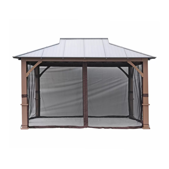
Laurel Hardtop Gazebo 3.05 m x 3.66 m / 10 ft x 12 ft
IMPORTANT. PLEASE READ CAREFULLY AND RETAIN FOR FUTURE REFERENCE
If you experience any product malfunction, defect or are missing any parts,
please contact our customer service department at 1-855-586-8118 or
servicec @ taipengchina.com. Our hours of operation are Monday - Friday,
8:30 AM to 5:30PM EST.
ITM. / ART. 2127014
-01-
-01-
Advertisement

Related Manuals for Costco 2127014


Summary of Contents for Costco 2127014
- Page 1 Laurel Hardtop Gazebo 3.05 m x 3.66 m / 10 ft x 12 ft ITM. / ART. 2127014 IMPORTANT. PLEASE READ CAREFULLY AND RETAIN FOR FUTURE REFERENCE If you experience any product malfunction, defect or are missing any parts, please contact our customer service department at 1-855-586-8118 or servicec @ taipengchina.com.
-
Page 2: Safety Information
SAFETY INFORMATION For the best assembly and usage experience, please read through all steps before attempting to assemble, operate or install the product • WARNING: It is the consumer’s responsibility to comply with any building codes, ordinances, zoning limitations, or local homeowner’s restrictions and obtain any required permit, before purchase and installation of the products. - Page 3 Components Post Base Cover Top Cover Left-Short Lintel Right-Short Lintel Left-Long Lintel Right-Long Lintel Connector Short Netting Tube Long Netting Tube Left-Support Bar Right-Support Bar Corner Piece Cover Lintel Cover Connector -03-...
- Page 4 Long-Top Bar Short-Top Bar Small Short-Top Bar Small Short-Top Bar Base Plate Base Cover Top Frame Top Connecting Tube Left Support Plate Right Support Plate Connecting Tube Hook Bracing Tube Corner cover Middle Supporting Tube Middle Supporting Tube -04-...
- Page 5 Left Supporting Tube Right Supporting Tube Left Support Small Tube Right Support Small Tube Left Big Top Cover Right Big Top Cover Big Top Cover Left Edge Band Right Edge Band Left Edge Band Right Edge Band Small Top Protective Edge Left Triangle Board Left Irregular...
- Page 6 Right Irregular Right Triangle Short Top Board - L Short Top Board - M Short Top Board - R Mosquito Netting Hardware Bolt\Flat Expansion bolt Washer (m6*15) Bolt\Flat Washer\ Nut Allen Wrench (m6*45) Bolt\Flat Allen Wrench Washer (m6*10) Bolt (m6*15) Sleeve Bolt\Flat Washer\ Nut...
- Page 7 Step 1 Fig 3 Fig 1 Fig 2 Fig 3 Fig 2 Fig 1 1.1. Insert the Base Cover (I) into the bottom post, connect the Base Plate (H) to the Post (A) with Bolt (AA), as seen in Fig 1; 1.2.
- Page 8 Step 2 Fig 4.1 Fig 4.2 Fig 4.3 Fig 4.4 C3/C4 Fig 4.5 2.1 Connect the Right Long Lintel (C4) and the Left Long Lintel (C3) with the Connector (D) and Bolt (AA), with Bolt (CC) at the top of the lintel, fix the Lintel Cover (F2) at the same time, as seen in Fig 4.1-Fig 4.4;...
- Page 9 Step 3 Fig 5.1 Fig 5.2 Fig 5.3 Fig 5.4 C1/C2 Fig 5.5 3.1 Connect the Right Long Lintel (C2) and the Left Long Lintel (C1) with the Connector (D) and Bolt (AA), with Bolt (CC) at the top of the lintel, fix the Lintel Cover (F2) at the same time, as seen in Fig 5.1-Fig 5.4;...
- Page 10 Step 4 Fig 7 C3/C4 Fig 6 Fig 8 4.1. Connect the Left and Right Long Lintels (C3 / C4) to the Top Cover (B) with Bolt (AA), as seen in Fig 6; 4.2. Connect Left-Support Bar (E1) to the Left-Long Lintel (C3) and the Post (A) with Bolt (AA), as seen in Fig 7;...
- Page 11 Step 5 Fig 9.1 Fig 10.1 Fig 9.2 Fig 10.2 Fig 9.1 Fig 9.2 Fig 10.1 Fig 10.2 5.1. Connect the Lintels (C1/C2) to the Top Cover (B) with Bolt (AA), as seen in Fig 9.1-Fig 9.2; 5.2. Connect the Left-Support Bar (E1) to the Left-Short Lintel (C1) and the Post (A) with Bolt (AA), as seen in Fig 10.1;...
- Page 12 Step 6 Fig 11.1-Fig 11.2 Fig 12 C2/C4 C1/C3 C2/C4 C1/C3 Fig 11.1 D1/D3 D2/D4 Fig 11.2 Fig 12 6.1. Connect the Corner Piece (F) to the Post (A) with Bolt (PP), as seen in Fig 11.1; 6.2. Connect the Cover (F1) to the Top Cover (B) with Bolt (AA) as seen in Fig 11.2; 6.3.
- Page 13 Step 7 Fig 13 7. Insert the Top Connecting Tube (K) into the Top Frame (J) with Bolt (AA), as seen in Fig 13. AAx4 -13-...
- Page 14 Step 8 Fig 17 L1/L2 Fig 14 Fig 15 Fig 16.1 Fig 16.2 8.1. Connect one end of the Left Support Plate (L1) and the Right Support Plate (L2) to the Connecting Tube (M) with Bolt (EE), then connect the other end to the Top Frame (J), as seen in Fig 14-Fig.15; 8.2.
- Page 15 Step 9 C2/C4 C1/C3 Fig 18 Fig 19 9. Connect one end of the Long-Top Bar (G1) to the Top Frame (J) with Bolt (AA), then connect the other end to the Corner Piece (F) with Bolt (BB), as seen in Fig 18-Fig 19. Note: Be sure measurements diagonally across the overall frame are within 5mm of the same distance after completing this step.
- Page 16 Step 10 C1/C2/C3/C4 Fig 20 Fig 21 10. Connect one end of the Short-Top Bar (G2) to the Top Frame (J) and Top Connecting Tube (K) with Bolt (AA),then connect the other end to the Lintels (C1/C2/C3/C4) with Bolt (AA), as seen in Fig 20-Fig 21.
- Page 17 Step 11 G3/G4 Fig 22.1 C1/C2/C3/C4 Fig 22.2 Fig 23 11. Connect the Connector (F3) to one end of the Small Top Bar (G3/G4) with Bolts (AA) and then to the Long-Top Bar (G1) with Bolts (AA); connect the other end to the Lintels (C1/C2/C3/C4) with Bolts (AA), as seen in Fig.
- Page 18 Step 12 P2/P4 P/P1 AA Fig 24 P3/P5 12.1. Connect one end of the Left Supporting Tube (P2) to the Long-Top Bar (G1) with Bolt (AA), then connect the other end to the Small Short-Top Bar (G3) with Bolt (AA); 12.2.
- Page 19 Step 13 R1/R2/ R3/R4 G2/G3/G4 Fig 25 13. Connect the Edge Bands(R1/R2/R3/R4) to the small short bars(G2/G3/G4) with Bolt(DD), as seen in Fig.25 R1x2 R2x2 R3x2 R4x2 DDx16 -19-...
- Page 20 Step 14 S1/S2/S3/S4/S5 Fig 28 R1/R2 Fig 26 the connect shape of steel top panel Fig 27 P1/P2/P3 14.1. As is shown in the graph, install the Top Boards (S1/S2/S3/S4/S5) in sequence, and have them fixed onto the Supporting Tubes (P1/P2/P3) one by one with Bolt (GG), as seen in Fig 26-Fig.27. Tips:Pls do not tighten all the screws until all the top boards are installed.
- Page 21 Step 15 Fig 30 S1/S5/S6/S7/S8 R3/R4 Fig 29 the connect shape of steel top panel P1/P2/P3/P4/P5 Fig 28 15.1.As is shown in the graph, install the Top Boards (S1/S6/S7/S8/S5) in sequence, and have them fixed onto the Supporting Tubes(P1/P2/P3/P4/P5) one by one with Bolt (GG), as seen in Fig 28-Fig.29.
- Page 22 Step 16 Q/Q1 Fig 31 16. Cover the Big Top Cover (Q/Q1) over the big top frame and tighten them with Bolt (FF), as seen in Fig 31. Q1x2 FFx8 -22-...
- Page 23 Step 17 Fig 32 17. Hang the Mosquito Netting (T) on the hook of the Netting Tube (D1/D2), as seen in Fig 32. -23-...
- Page 24 Step 18 Fig 33 18.Using an electric concrete drill,drill holes into the concrete floor,corresponding to the holes in Base Plates(H). Insert Expansion bolt (II) into the holes and hammer into place, using a hammer. Fasten Expansion bolts (II),make sure the base plates (H) are totally grounded,as seen in Fig 33. IIx16 -24-...
-
Page 25: Care And Maintenance
This warranty does not affect your statutory rights. In case of any malfunction of your COSTCO product (failure, missing part, etc.), please contact one of our service technicians at our toll-free service line at 1-855-586-8118 from EST 9 AM to 5 PM, Monday to Friday.
Need help?
Do you have a question about the 2127014 and is the answer not in the manual?
Questions and answers