
Related Manuals for AVL DITEST COUNTER


Summary of Contents for AVL DITEST COUNTER
- Page 1 USER MANUAL AVL DiTEST COUNTER ID number: AT8008EN Revision: Edition: 09/2021 Software version: Data subject to change and errors. All data valid at the time of publication. PASSION INNOVATES FUTURE...
- Page 3 AVL DiTEST Counter AVL DiTEST GmbH Alte Poststrasse 156 A-8020 Graz / AUSTRIA Tel.: +43 316 787-0 Fax: +43 316 787-1460 ditest@avl.com www.avlditest.com Copyright © 2021 AVL DiTEST GmbH, all rights reserved. User manual...
-
Page 4: Table Of Contents
Design ..........................8 Scope of supply ......................11 Commissioning ......................12 Hardware .......................... 12 Software ..........................15 Working with the AVL DiTEST Counter ............... 16 DSS controlled ........................16 6.1.1 Connecting to the AVL DiTEST DSS ................16 Stand-alone mode ......................17 6.2.1... -
Page 5: General
1.2 Intended Use The AVL DiTEST Counter is used to test the particulate filters of motor vehicles. To do so, the device determines the particle count in the exhaust gas flow. -
Page 6: Safety
Safety AVL DiTEST Counter 2 Safety This manual contains important warnings and safety instructions that must be observed by the user. Non-observance of the information on these dangers can lead to death or serious injury. 2.1 Safety Instructions and Warning Signs... -
Page 7: General Safety Instructions
AVL DiTEST Counter Safety Notices: Notice This term refers to situations or operating errors that can lead to damage or data loss. Information This term indicates important information or instructions. Failure to follow these instructions will significantly prevent or hinder the successful execution of the actions described in this documentation. - Page 8 Safety AVL DiTEST Counter ➢ Only use accessories recommended by the manufacturer. ➢ Secure the vehicle sufficiently against rolling away. ➢ The plug of the heating hose may only be used to plug in the heating hose. User manual...
-
Page 9: Safety Concept
AVL DiTEST Counter Safety 2.3 Safety Concept WARNING Danger due to harmful or irritant substances Measurements taken while the engine is running can release substances that are hazardous to health. When measuring with the engine running in closed rooms (workshops, test halls, etc.), discharge the vehicle exhaust gases and ensure sufficient ventilation in the rooms. - Page 10 Safety AVL DiTEST Counter WARNING Danger to life due to electrical voltage Maintenance is must only be performed with the device switched off and disconnect power plug. User manual...
- Page 11 AVL DiTEST Counter Safety NOTICE Observe the applicable manufacturer's specifications when maintaining the adjustment speed of diesel engines. NOTICE Always switch off the ignition before connecting or disconnecting the OBD plug / the different AVL DiTEST vehicle adapters. NOTICE Never leave the probe lying on the ground. Make sure that neither liquids (e.g. water) nor other impurities get into the exhaust gas measuring device via the probe.
-
Page 12: Design
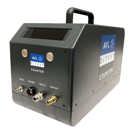
AVL DiTEST Counter Design AVL DiTEST Counter, Front View The following figure shows the front of the device: Fig. 1: Front view of the AVL DiTEST Counter (exemplary) LC display Control buttons HEATING (hose heating connection) GAS IN, exhaust gas inlet/probe connection... - Page 13 AVL DiTEST Counter Design AVL DiTEST Counter, Rear View The following figure shows the rear of the device: Fig. 2: Rear view of the AVL DiTEST Counter (exemplary) “Power” switch Mains plug connection “USB Type B” port “USB Type A” port...
- Page 14 Design AVL DiTEST Counter Power Cable Fig. 3: Power cable (exemplary) Exhaust Gas Probe Fig. 4: Sampling line of the AVL DiTEST Counter (exemplary) Probe tip Handle for exhaust probe mount Heating hose with connections User manual...
-
Page 15: Scope Of Supply
AVL DiTEST COUNTER Scope of Supply 4 Scope of Supply The following table gives an overview of the scope of supply: ● AVL DiTEST Counter ● ● Power cable, country specific (Example: C13 Euro power cable) ● ● Exhaust gas probe Heating hose ●... -
Page 16: Commissioning
Commissioning AVL DiTEST Counter Commissioning Hardware Site of Installation WARNING Explosion or fire hazard due to gases and/or vapours The device must not be operated near open fuel tanks, as otherwise there is a risk of explosion or fire due to gases and/or vapours. - Page 17 Insert the mains plug into a plug socket. Switch on the AVL DiTEST Counter with the power switch (1). When the device starts, the AVL DiTEST Counter displays the bootloader and firmware version and performs a self-test. The device then warms up and switches to standby mode.
- Page 18 Commissioning AVL DiTEST Counter Exhaust Gas Probe, Hose Fig. 6: Connecting the AVL DiTEST Counter on the front side WARNING Risk of burns from hot parts The heating hose connection heats up to over 55 °C. Wear safety gloves when handling the hose.
-
Page 19: Software
We recommend connecting an exhaust air bypass to "GAS OUT". The connection is a standardised compressed air quick coupling with a nominal diameter of 7.2. Software AVL DiTEST DSS is installed and updated via AVL DiTEST DSS. Please refer to the document AT7260 DSS Installation and update. User manual... -
Page 20: Working With The Avl Ditest Counter
Working with the AVL DiTEST Counter DSS Controlled Connecting to the AVL DiTEST DSS 6.1.1 The primary operating mode is the connection of the AVL DiTEST Counter to the AVL DiTEST DSS. Please refer to the AT7683 AVL DiTEST DSS user manual. User manual... -
Page 21: Stand-Alone Mode
Stand-Alone Mode 6.2.1 Screen Symbols Operation of the AVL DiTEST Counter in stand-alone mode is done by the two buttons and the display. The following symbols occur on the bottom of the display to show the status of the device at a first glance:... - Page 22 Working with the AVL DiTEST Counter AVL DiTEST Counter Selftest To perform a self-test, proceed as follows: 1. Press the right button in standby mode. Fig. 7 2. Press the left key to select the selftest. Fig. 8 3. Wipe the probe tip with a cloth.
-
Page 23: Apk Procedure (Official Measurement)
AVL DiTEST Counter Working with the AVL DiTEST Counter Fig. 11 6.2.3 APK Procedure (Official Measurement) The particle counter firmware program automatically guides the device operator through the measurement procedure as described below: Hardware 1. Start the device as described in section 2. - Page 24 Working with the AVL DiTEST Counter AVL DiTEST Counter 5. Select a limit for the vehicle by either selecting one from the list or by entering it manually. Press and then Fig. 14 Information In device settings, elements can be shown and hidden.
- Page 25 AVL DiTEST Counter Working with the AVL DiTEST Counter Fig. 18 Information If the measured value immediately exceeds double the limit value, after the probe has been inserted into the exhaust, measurement procedure may be aborted, and the test was not passed.
-
Page 26: Operation
Working with the AVL DiTEST Counter AVL DiTEST Counter 6.2.4 Operation To perform a measurement in stand-alone mode, proceed as follows: Hardware 1. Start the device as described in section 2. Press Press to scroll to the item Measure. Press Fig. - Page 27 AVL DiTEST Counter Working with the AVL DiTEST Counter Fig. 22 5. Press the right key to end the measurement. The measurement is terminated and the device returns to standby mode. 6.2.4.1 Logbook 1. Press 2. Press to scroll to the Logbook item.
- Page 28 Working with the AVL DiTEST Counter AVL DiTEST Counter Fig. 25 6. Press to scroll to the End item. 7. Press to return to the menu. 6.2.4.2 Language 1. Press 2. Press to scroll to the Language item. 3. Press Fig.
- Page 29 AVL DiTEST Counter Working with the AVL DiTEST Counter Fig. 27 4. Make the desired settings and press to accept them and then to return to the menu. 6.2.4.4 Info 1. Press 2. Press to scroll to the Info item.
-
Page 30: Maintenance
CAUTION Risk of burns due to hot surface After switching off the device, allow it to cool down before starting maintenance work. The AVL DiTEST Counter must be maintained according to specifications. The half-yearly maintenance must be documented: ▪ On the maintenance sticker of the respective device with date and name. -
Page 31: Visual Inspection
Perform a visual inspection at regular intervals. During each visual inspection the device must be checked for the following conditions: • Soiling → see Cleaning • Wear • Regularly check all parts for damage • Damage and leakage of media lines Notice Only use accessories approved by AVL DiTEST. User manual... -
Page 32: Maintenance Schedule
Maintenance AVL DiTEST Counter Maintenance Schedule Subsequent maintenance procedures must be carried out as required, but at the latest within the following maintenance cycles: Note: Maintenance work ● Sec. 7.3 Cleaning ● Sec. 7.4 USB cable ● Sec. 7.5 Exhaust gas probes ●... -
Page 33: Cleaning
Clean the exhaust probe with compressed air. External Visual Inspection Inspect all components for damage (e.g. breakage) and soiling. Check all cables regularly for damage. WARNING Danger due to defective parts Replace the power cable if damaged. Only use original AVL DiTEST spare parts. User manual... -
Page 34: Filter
Maintenance AVL DiTEST Counter Filter WARNING Danger to life due to electrical voltage Maintenance is generally performed with the device switched off. After switching off the device, also disconnect the power plug. Visually check the filters. If the filters are dirty, the required flow rate can no longer be achieved, and the pump speed fluctuates. - Page 35 AVL DiTEST Counter Maintenance 3. Open the filter using a suitable screwdriver. You can also use a coin (2 Euro) or a pliers. 4. Pull out the filter with cover. Fig. 32 5. Remove the old filter tube and place the new filter on the filter cover.
-
Page 36: Calibration
Maintenance AVL DiTEST Counter 7.8 Calibration The AVL DiTEST Counter must be calibrated annually. The calibration must be documented in the inspection log. The annual maintenance (with calibration service) can be performed by AVL DiTEST Aftersales. User manual... -
Page 37: Warranty
Incorrect operation (e.g. operating the display with sharp or pointed objects) ■ Incorrect storage, maintenance and care. Case of Damage In the event of damage, please contact the respective AVL DiTEST branch / AVL DiTEST partner in your country. Errors and Error Elimination Open the system information (service screen). -
Page 38: Fault, Symptom, Cause And Remedy
Errors and Error Elimination AVL DiTEST Counter Fault, Symptom, Cause and Remedy Error code Error text Possible cause Solution/hint 10102 Stabilization timeout. 20202 The voltage at the Corona is The Corona is getting polluted. Contact the service very high. hotline. - Page 39 AVL DiTEST Counter Errors and Error Elimination 30402 The internal 3.3 V power Contact the service supply does not work. hotline. 30403 The circuit board temperature The temperature of the internal Turn off the device is too high. circuit board is too high.
- Page 40 Errors and Error Elimination AVL DiTEST Counter 31009 The exhaust probe is blocked. Check the exhaust probe. 31204 The calibration is expired. Schedule a calibration appointment immediately. A measurement can only be performed after a new calibration. 31501 Error when accessing the SD The SD card is defective.
-
Page 41: Problem Reports / Service Addresses
AVL DiTEST Counter Errors and Error Elimination Problem Reports / service addresses In the event of damage, please contact the respective AVL DiTEST branch / AVL DiTEST partner in your country. User manual... -
Page 42: Technical Data
Technical Data AVL DiTEST Counter Technical Data VARIOUS Measuring principle Diffusion Charging Volatile particle remover Evaporation Tube Warm up time Approx. 5 min 5 … 40 °C Operating temperature 0 … 50 °C Storage temperature 10 … 90 % non-condensing up to 95 % condensing... -
Page 43: Ce - Declaration Of Conformity
AVL DiTEST Counter Technical Data 10.2 CE - Declaration of Conformity This device complies with the required standards. The declaration of conformity can be requested on demand. User manual... -
Page 44: Index
Index AVL DiTEST Counter Index Calibration ..............33 Plausibility check ............1 Cleaning ..............27 Problem reports / service addresses ......39 Commissioning ............11 Result ................. 22 Errors and error elimination ........35 Errors, symptoms, causes and elimination ....36 Exhaust gas probe ............
Need help?
Do you have a question about the COUNTER and is the answer not in the manual?
Questions and answers