Sign In
Upload
Download
Table of Contents
Contents
Add to my manuals
Delete from my manuals
Share
URL of this page:
HTML Link:
Bookmark this page
Add
Manual will be automatically added to "My Manuals"
Print this page
×
Bookmark added
×
Added to my manuals
Manuals
Brands
DeWalt Manuals
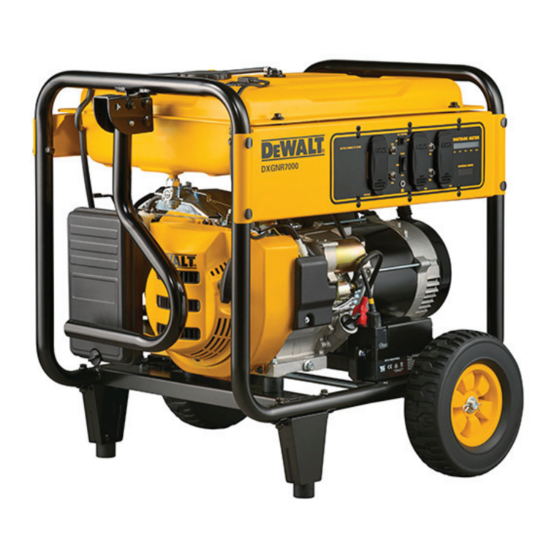
Portable Generator
DXGN4500
Manual
DeWalt DXGN4500 Manual
Hide thumbs
1
2
Table Of Contents
3
4
5
6
7
8
9
10
11
12
13
14
15
16
17
18
19
20
21
22
23
24
25
26
27
28
29
30
31
32
33
34
35
36
37
38
39
40
41
42
43
44
45
46
47
48
49
50
51
52
53
54
55
56
page
of
56
Go
/
56
Contents
Table of Contents
Troubleshooting
Bookmarks
Table of Contents
Read this Manual Thoroughly
Replacement Parts
Table of Contents
Section 1 Capacitive Discharge (Brushless)
Introduction
Rotor Assembly
Stator Assembly
Circuit Breakers
Operation
Troubleshooting Flowcharts
If Problem Involves AC Output
Problem 1 - Generator Produces Zero Voltage or Residual Voltage
Problem 2 - Voltage & Frequency Are both High or Low
Problem 3 - Excessive Voltage/Frequency Droop When Load Is Applied
Problem 4 - Generator Produces High Voltage at No-Load
AC Diagnostic Tests
Test 1 - Check No-Load Voltage and Frequency
Test 2 - Check Main Circuit Breaker
Test 3 - Check Continuity of Receptacle Panel
Test 5 - Field Flash Alternator
Test 6 - Check Capacitor
Test 7 - Test Brushless Excitation Winding
Test 8 - Test Brushless Stator Windings
Test 10 - Check Load Voltage and Frequency
Test 11 - Check Load Watts and Amperage
Section 2 Direct Excitation (Brush Type)
Introduction
Stator Assembly
Brush Holder and Brushes
Voltage Regulator
Operation
Troubleshooting Flowcharts
If Problem Involves AC Output (Brush Type)
Problem 5 - Generator Produces Zero Voltage or Residual Voltage
Problem 6 - Voltage & Frequency Are both High or Low
Problem 7 - Excessive Voltage/Frequency Droop When Load Is Applied
Problem 8 - Generator Produces High Voltage at No-Load
AC Diagnostic Tests
Test 1 - Check No-Load Voltage and Frequency
Test 2 - Check Main Circuit Breaker
Test 3 - Check Continuity of Receptacle Panel
Test 4 - Fixed Excitation Test/Rotor
Amp Draw Test
Test Brushed Stator Windings
Test 10 - Check Load Voltage and Frequency
Test 11 - Check Load Watts and Amperage
Test 12 - Adjust Voltage Regulator
Section 3 Engine Diagnostic Tests
Introduction
Problem 9 - Recoil Cord will Not Pull
Problem 10 - Engine Starts Hard and Runs Rough
Problem 11 - Engine Turns over but will Not Start
Problem 12 - Engine "Hunts" / Erratic Idle
Problem 13 - Engine will Not Crank
Problem 14 - Recoil Cord will Not Pull (if so Equipped)
Problem 15 - Engine Cranks but will Not Start
Problem 16 - Engine Starts Hard and Runs Rough
Problem 17 - Engine Starts then Shuts down
Problem 18 - Battery will Not Charge
Problem 19 - Engine "Hunts" / Erratic Idle
Problem 20 - Unit will Not Idle
Problem 21 - Unit RPM will Not Increase from Idle
Problem 22 - no Display from Wattage/Runtime Meter
Problem 23 - Wattage/Runtime Meter Display Is Flashing Erroneous Data
Introduction
Test 14 - Check Fuse
Test 15 - Check Battery & Cables
Test 16 - Check Voltage at Starter
Contactor (SC)
Test 17 - Check Start-Run-Stop Switch
Test 18 - Test OFF-ON Switch
Test 19 - Check Starter Motor
Test 20 - Check Ignition Spark
Test 21 - Check Spark Plug(S)
Test 22 - Check Carburetion
Test 23 - Choke Test
Test 24 - Check Valve Adjustment
Test 25 - Check Engine / Cylinder Leak down
Test / Compression Test
Test 26 - Check Ignition Coil
Test 27 - Check Flywheel
Test 28 - Remove Shutdown Wire
Test 30 - Check / Adjust Governor (Mechanical)
Test 31 - Check Oil Pressure Switch
(If Equipped)
Test 32 - Check Oil Level Switch (if Equipped)
Test 33 - Test Recoil Function
Test 34 - Test Engine Function
Test 35 - Test Battery Charger
Test 36 - Test Idle Control
Section 4 Major Disassembly
Section 5 Electrical Data
Advertisement
Quick Links
1
Replacement Parts
Download this manual
DIAGNOSTIC
REPAIR
MANUAL
DeWalt Series Portable Generators
P O R T A B L E G E N E R AT O R S
M o d e l s :
D X G N 4 5 0 0
D X G N 6 0 0 0
D X G N 7 2 0 0
D X G N 1 4 0 0 0
D X G N R 5 7 0 0
D X G N R 7 0 0 0
Table of
Contents
Previous
Page
Next
Page
1
2
3
4
5
Advertisement
Table of Contents
Troubleshooting
Troubleshooting Flowcharts
7
Troubleshooting Flowcharts
17
Need help?
Do you have a question about the DXGN4500 and is the answer not in the manual?
Ask a question
Questions and answers
Related Manuals for DeWalt DXGN4500
Inverter DeWalt DXGN14000 User Manual
(8 pages)
Inverter DeWalt DXGN7200 Insert
(7 pages)
Portable Generator DeWalt DXGN Series Operator's Manual
(323 pages)
Portable Generator DeWalt DXGN Series Instruction Manual
(17 pages)
Portable Generator DeWalt DXGN Series Use And Maintenance Manual
(61 pages)
Portable Generator DeWalt DXGN Series Instruction Manual
(40 pages)
Portable Generator DeWalt DXGNR 7000 Instruction Manual
(72 pages)
Portable Generator DeWalt DXGNR 5700 Instruction Manual
(80 pages)
Portable Generator DeWalt DXGNR 6500 Instruction Manual
(80 pages)
Portable Generator DeWalt DXGNR4000 Instruction Manual
(24 pages)
Portable Generator DeWalt DXGNR7000 Manual
(56 pages)
Portable Generator DeWalt DXGNi20E Owner's Manual
(40 pages)
Portable Generator DeWalt DXGNi35E Owner's Manual
(36 pages)
Portable Generator DeWalt DXGNP30E Owner's Manual
(36 pages)
Portable Generator DeWalt DXGNP65E Owner's Manual
(36 pages)
Portable Generator DeWalt DXGNP85E Owner's Manual
(36 pages)
This manual is also suitable for:
Dxgn6000
Dxgn7200
Dxgn14000
Dxgnr5700
Dxgnr7000
Pd422mhi005
...
Show all
Pd532mhi005
Pd612mhb005
Pd123mhb007
Pm0167000.01
Pm0165700.01
Table of Contents
Print
Rename the bookmark
Delete bookmark?
Delete from my manuals?
Login
Sign In
OR
Sign in with Facebook
Sign in with Google
Upload manual
Upload from disk
Upload from URL


Need help?
Do you have a question about the DXGN4500 and is the answer not in the manual?
Questions and answers