Advertisement
Quick Links
Advertisement

Subscribe to Our Youtube Channel
Related Manuals for Matrix Cosec Door


Summary of Contents for Matrix Cosec Door
- Page 1 COSEC DOOR Quick Start S E C U R I T Y S O L U T I O N S...
-
Page 3: Door Controller
S E C U R I T Y S O L U T I O N S COSEC DOOR Door Controller Quick Start... -
Page 4: Before You Start
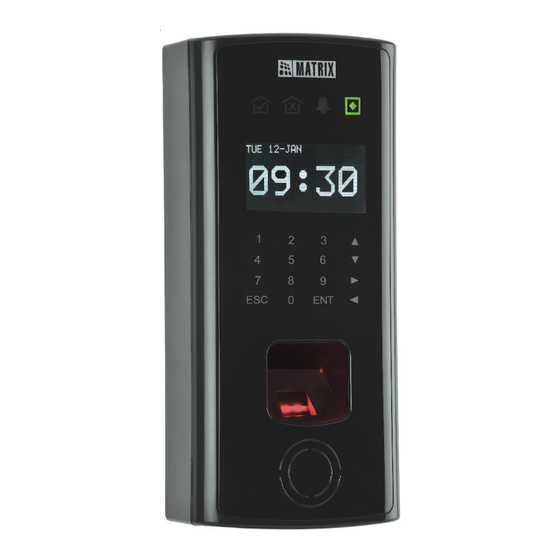
Congratulations on choosing the Matrix COSEC DOOR Controller. This quick start guide is meant to help you in completing the installation of the COSEC DOOR Controller Hardware components. For detailed information on the installation and configuration of the COSEC system, you may... - Page 5 Know your COSEC DOOR The COSEC DOOR can be configured as a PANEL DOOR or DIRECT DOOR and are designed to control a single Door. The PANEL DOOR, as the name suggests connects to the COSEC PANEL which in turn connects to the COSEC Monitor application.
- Page 6 FP ID from finger print identification modules and PIN code input through the touch sense keypad. In addition to the above, the COSEC DOOR is designed to support Request for Exit through EXIT switch or through an Exit reader (interfaced through RS232/Wiegand port).
- Page 7 However, the system supports a total of 75 PANEL DOORs in a heterogeneous network under one PANEL. Mounting and Wiring the COSEC DOOR Before installing the COSEC DOOR: The COSEC DOOR has been designed to be mounted on a wall in a single box without any additional enclosure.
- Page 8 • COSEC DOOR Controller with accessory kit (included) as mentioned earlier. • Matrix COSEC Door PSBB (13.8VDC @ 2 A Universal Mains PS with Battery Backup) is not included with the package but has to be ordered separately in the event of a requirement for battery backup for the COSEC DOOR.
- Page 9 In the event of the MATRIX COSEC RF module also being included in the ordered items, the module needs to be mounted on the COSEC DOOR prior to starting the wall mounting procedure as shown. Step 3: Power Supply There are three options for providing the 12VDC @ 1 amp power input to the COSEC DOOR Controller.
- Page 10 Power Supply Up to 4 Door Controllers 2. Connect the adapter giving an output of 12VDC @ 1~1.5A to the terminals 39 and 40 on the COSEC DOOR Controller unit. However, care must be taken to maintain the correct polarity. +12V...
- Page 11 3. Connect the two cables coming from the Matrix PSBB- Universal Mains Power supply (13.8 VDC @ 2A) with battery backup to the terminals 39 and 40 on the COSEC DOOR terminal strip. Here again, care must be taken to maintain the correct polarity.
- Page 12 The lock NO, COM, NC and +12VDC terminals are located at terminal nos. 21, through to 24 on the top right of the COSEC DOOR terminal strip. The locking device output is controlled by the software according to preset parameters for allowing access or unlocking doors according to schedules and access levels.
- Page 13 NC/NO and the 0V (terminal 25) to the Door locking device. Step 6: Hooking up Inputs The COSEC DOOR has on-board capacity of 4 inputs (2 in the case of a DIRECT DOOR configuration). Except for the Request to Exit Input, each input can be supervised with end-of-line resistors (4.7K ohm).
- Page 14 External Reader Wiring The COSEC DOOR supports a maximum of 3 readers (2 internal and one External). The External reader port supports a single reader with Wiegand / Serial interface. To fully utilize Wiegand reader port, a shielded 11-conductor cable (18-22 AWG) is required.
- Page 15 the following are the connection diagrams for the serial and the wiegand readers.
- Page 16 Connecting the External Serial Readers: Connect the Matrix COSEC Readers to the COSEC DOOR terminal strip as shown in the figure below. The terminals on the back of the COSEC reader unit are numbered 1 through 11/15 (depending on the reader) as shown and are to be connected to the terminal strip of the DOOR using at least a 11 conductor 22 AWG cable.
- Page 17 Terminal Connections for External Reader options COSEC READER FPR Terminal Strip of Door Controller The COSEC Mifare and the Proximity reader modules can be connected in the following ways depending on the kind on the interface type of the reader.
- Page 18 Rdr pwr DATA RTN Green LED Red LED Beeper Hold Tamper RS-232 R RS-232 T Status LED Alarm LED Exit SW External Serial Reader Terminal Strip of Door Controller Rdr pwr DATA RTN Green LED Red LED Beeper Hold Tamper RS-232 R RS-232 T Status LED...
- Page 19 Refer the reader installation procedure for proper power connection. Step 7: Connecting the DOOR Controller to the RS-485 Bus Door Controllers are linked together through their RS-485 Loop IN and Loop Out terminals or the Ethernet port in the event of using the TCP/IP connectivity option. The maximum communication loop length in the case of an RS485 option with the appropriate cable is 1.2 kilometers (4,000 feet) from the last controller to the workstation.
- Page 20 This is located at the lower right on the rear of the COSEC DOOR as shown. Also set the number of the door controller by setting the dip switch provided at the top right on the back of the PANEL DOOR Controller as shown.
- Page 21 initialize the IP settings, Password and System Parameters of the DIRECT DOOR to factory defaults. 2. The Ethernet RJ45 connector is located just above the terminal strip on the back of the Door Controller. Connect the male RJ45 connector here in the event of the DIRECT DOORs or the Ethernet connectivity option being used for the PANEL DOORs.
- Page 22 DOOR Mounting Guide...
- Page 23 Place the Mounting plate on the wall and mark the points for drilling holes for the four wall mounting screws M 7/30. Drill a hole of appropriate size and place the nail grips in the holes. Now place the mounting plate on the wall and mount it using the 4 wall mounting screws M 7/30.
- Page 24 Once all the connections are checked, power up the Door Controller which in turn will go through the booting process. The LCD display will first display the Matrix logo followed by the firmware version, RS485 address of the controller as set on the dip switch and the MAC address of the door controller for a few seconds.
- Page 25 navigate to the Admin option on the DOOR using the keypad and display. The Admin option is password protected and gives access to the following administrative functions on the DIRECT DOOR: • LAN Settings • Set Date and Time • Door •...
- Page 26 MON 21-DEC 15:22 MON 21-DEC 15:22 1 LAN Settings 1 IP: 192.168.50.50 2 Set Date and Time 2 SM: 255.255.255.0 3 Door 3 GW: 4 Password Admin LAN Setting Select the LAN Settings option by pressing the ENT key at the above display or pressing the Number key 1.
- Page 27 press the Number key 3 to select the SM option or scroll the option and press the ENT key. The system will prompt the new Gateway IP address. Key in the new IP settings for the above parameters as shown in the above display. The system will display the status of the updated settings and return to the default screen.
- Page 28 one connector to the input signals on the other connector. This allows the computer and the Door to perform full-duplex Ethernet communication. Crossover/Straight Cable DIRECT DOOR COSEC Monitor PC Once the IP address of the DIRECT DOOR has been changed from its display as explained, proceed with the further configuration of the DOOR Controller as explained in the COSEC System Manual.
- Page 29 It is essential to maintain the polarity of the terminals while connecting the power supply options to the DOOR Controller.
- Page 32 S E C U R I T Y S O L U T I O N S MATRIX COMSEC PVT. LTD. Corporate Office: 394-GIDC, Makarpura, Vadodara - 390010, India. Ph.:+91 265 2630555, Fax: +91 265 2636598 E-mail: Info@MatrixComSec.com Factory: 39-GIDC, Waghodia - 391760, Dist. Vadodara, India.
Need help?
Do you have a question about the Cosec Door and is the answer not in the manual?
Questions and answers