Table of Contents
Advertisement
Quick Links
Advertisement
Table of Contents

Summary of Contents for Bergey VCSII
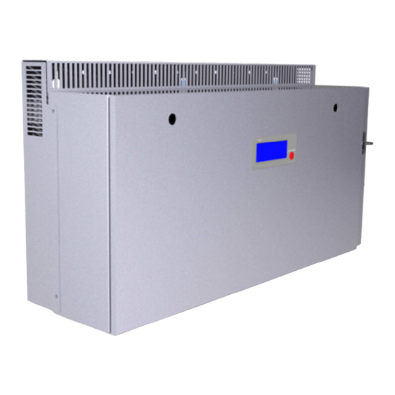
- Page 1 VCSII – Battery Charger Bergey WindPower Co. Owner’s Manual Rev: 0 June 17, 2016...
-
Page 2: Table Of Contents
Table of Contents Important Safety Instructions ........................3 VCS II Mounting ............................4 VCS II User Interface ............................ 6 VCS II User Configuration ..........................7 VCS II Can Bus Interface ..........................12 VCS II CAN Bus Message Specification ....................12 VCS II Status, Faults, &... -
Page 3: Important Safety Instructions
Hazard or unsafe practice which could cause product damage. WARNING: SAVE THESE INSTRUCTIONS This manual contains important instructions for the VCSII that shall be followed during installation and maintenance of the converter. The output field wiring terminal (Battery) can be used for connection of a maximum of:... -
Page 4: Vcs Ii Mounting
VCS II User Guide – Bergey WindPower Co. VCS II Mounting WARNING: Confirm factory default settings are appropriate for you battery bank prior to commissioning to avoid potential battery damage. See the “VCS II User Configuration” section. The internal portion of the enclosure is sealed with no need for ventilation. The heatsinks, breaker and external inductors are re not sealed to the enclosure and results in a NEMA 1 rating. - Page 5 To install the VCSII enclosure on the bracket, partially put the two top screws (M6x20) on both sides of the enclosure. They will be used to hang the unit on the bracket. Carefully lift the enclosure placing close attention to the rear magnetics so they are not damaged.
-
Page 6: Vcs Ii User Interface
VCS II User Guide – Bergey WindPower Co. VCS II User Interface The charge controller user/operator control input interface consists of a single push button on the front panel of the charge controller. The single push button performs different functions depending on the controller system state and operating mode and the length of time that the button is pressed. -
Page 7: Vcs Ii User Configuration
The VCS II user configurable parameters are stored on the SD card along with other files which should not be altered without consultation of Bergey WindPower Co. The file user_cfg.txt is tab delimited and allows setting all of the configuration settings. The file may be easily configured with any text file editor. - Page 8 VCS II User Guide – Bergey WindPower Co. There is a fault log stored on the SD card for all faults encountered- fltsxxxx.csv. The highest number xxxx is the latest fault log. Basic data surrounding the fault are stored. Additionally there is high resolution scope data files created during each fault.
- Page 9 VCS II User Guide – Bergey WindPower Co. Rev: 0 June 17, 2016...
- Page 10 VCS II User Guide – Bergey WindPower Co. The long term data files are stored by default at 10 minute intervals; there is no real time clock in the VCS II so the on time is stored in the first column, with the cumulative energy in kWh stored in the second column.
- Page 11 B. The frequency must be given in 1 Hz increments up to 150 Hz. Changes to the power curve should not be made without Bergey WindPower Co approval, as damage to the controller or the alternator can occur if improper values are used.
-
Page 12: Vcs Ii Can Bus Interface
VCS II User Guide – Bergey WindPower Co. VCS II Can Bus Interface The CAN Bus utilizes an isolated input to provide a galvanic isolation rating of 2500 V . An RJ45 connection (CN20) is provided on the controller with a pinout of: Pin 1 –... - Page 13 VCS II User Guide – Bergey WindPower Co. Message Request Response Comment DLC: 4 DLC: 8 The external controller sends this • Mailbox 2 is reserved Mailbox 18 is reserved message to DSP to request certain to receive this to send the parameter parameter.
- Page 14 VCS II User Guide – Bergey WindPower Co. 5. Parameter ID Specifications: Parameter ID Description Data (PID) Type High Limit battery voltage target allowed [Vdc] Float32 Lo Limit battery voltage target allowed [Vdc] Float32 Max output current limit allowed [Adc]...
-
Page 15: Vcs Ii Status, Faults, & Warnings
VCS II User Guide – Bergey WindPower Co. VCS II Status, Faults, & Warnings The faults and warning messages are basically coded as binary bits, such that multiple faults and warnings can be transmitted. There will be an integer value returned for fault and warning queries. -
Page 16: Vcs Ii Fault List
VCS II User Guide – Bergey WindPower Co. VCS II Fault List Fault (PID 30 & 31) Hex Code 0x00000001 Fault, over current chopper 1 [na] 0x00000002 Fault, over current chopper 2 [na] Fault, over current chopper 3 [na] 0x00000004... -
Page 17: Vcs Ii Warning List
VCS II User Guide – Bergey WindPower Co. VCS II Warning List Warning (PID 32) Hex Code MS_OUTPUT_POWER 0x00000001 MS_BAT_FULL_CHARGED 0x00000002 MS_SD_MISSING 0x00000004 MS_THERMAL_ACTIVE 0x00000008 MS_CAN_COMM_ERROR 0x00000010 MS_EQUALIZE_MODE 0x00000020 MS_SD_PROTECTED 0x00000040 MS_LOW_SPEED 0x00000080 MS_MANUAL_MODE 0x00000100 MS_BAT_VOL_LOW 0x00000200 MS_BAT_TEMP_HIGH 0x00000400 MS_PHASE_ROTATION... -
Page 18: Vcs Ii Specifications
VCS II User Guide – Bergey WindPower Co. VCS II Specifications Turbine Input Input current (max) 43 Amps Input voltage (max) 480 Vrms Input start voltage minimum (at low battery condition) 30 Vrms Input normal operating voltage range 35 Vrms – 480 Vrms Input frequency range 0 –... -
Page 19: Performance
VCS II User Guide – Bergey WindPower Co. Performance Rated power (11 m/s) 8 kW Rated RPM Rated windspeed 11 m/s Start-up windspeed 4 m/s Cut-in windspeed 1.8 m/s Cut-out windspeed none Furling windspeed 16-18 m/s Max design windspeed 60 m/s...