
Related Manuals for CEStronics AccessOne TSG8

Summary of Contents for CEStronics AccessOne TSG8
- Page 1 AccessOne Door controllers Door controller TSG8 Assembly and operating manual English Version VA1 BRO2323 www.ces.eu...
-
Page 2: Table Of Contents
Contents 1 About this manual 1.1 Manufacturer and service 1.2 Target groups of this manual 2 For your safety 2.1 EU Declaration of Conformity 2.2 Intended use 2.3 Basic safety instructions 3 About the TSG door controller 3.1 Operating elements and part designations 4 Assembly 5 Connections and wiring 5.1 RS485 –... -
Page 3: About This Manual
1 About this manual This manual contains information on the installation and commissioning of a TSG door controller in the AccessOne access control system. Other applicable documents Setup BRO2316_Instructions_AccessOne This manual should be treated as a part of the product and must be kept for the entire service life of the product. The manual should be passed on to any subsequent user or owner of the product. -
Page 4: Target Groups Of This Manual
Knowledge of the risks associated with handling sensitive electronic components Personnel with have received training on the product by CES or a CEStronics partner. Here the personnel are given detailed and specific information to prepare them for the required task. -
Page 5: For Your Safety
2 For your safety 2.1 EU Declaration of Conformity The EU declaration of conformity can be obtained from the manufacturer. 2.2 Intended use The TSG door controller is used for monitoring and controlling doors in an AccessOne access control system. The product is intended solely for and may only be used for this purpose. -
Page 6: Basic Safety Instructions
2.3 Basic safety instructions This device has been built using state-of-the-art technology and recognised safety rules. Nevertheless, its use may result in hazards for the user or third parties, or also have negative impacts on the device and other material assets. Use the product only while it is in proper working order and only for its intended purpose, taking due account of safety and potential hazards, and in accordance with the operating manual. - Page 7 Incorrect or neglected maintenance and repair can result in the device not functioning correctly or not functioning at all. ✓ Have the device maintained and checked for proper functioning every six months by CES or a CEStronics partner. ✓ Always have repairs performed by qualified personnel.
-
Page 8: About The Tsg Door Controller
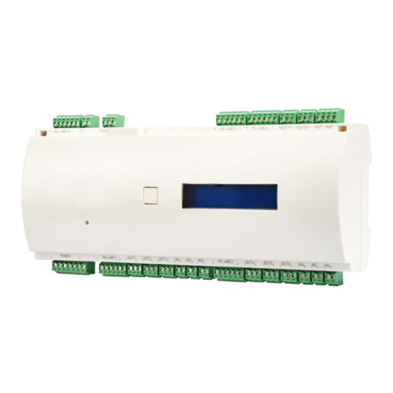
3 About the TSG door controller The TSG8/Compact door controller monitors and controls up to eight doors (and its inputs and outputs can be expanded to 56 channels). Each TSG8 can be connected to a total of 32 readers or wall terminals. Lifts can also be controlled over up to 32 floors by means of contacts. - Page 9 RJ45 connector 1-button menu navigation SD card slot Jumpers Reset button www.ces.eu...
-
Page 10: Assembly
4 Assembly Target group of this section:: CEStronics partners Electricians Electricians with product training IT/administration specialists The door controller is mounted on DIN rails. www.ces.eu... -
Page 11: Connections And Wiring
5 Connections and wiring Target group of this section:: CEStronics partners Electricians Electricians with product training IT/administration specialists Risk of damage. Before working on or in the device, ensure that it is isolated from the power supply. 5.1 RS485 – Tamper – RS232 – Power For the connection of additional contacts, e.g. - Page 12 5.1.3 RS232 Connection Function Receive data cable for outgoing data (negative logic) Transmit data cable for outgoing data (negative logic) Ground. The signal voltages are measured against this cable. 5.1.4 Power Connection Function +12 V DC Power supply Shield Ground. The signal voltages are measured against this cable. AC fail (low active) Battery low (low active) Ground.
- Page 13 5.1.5 Reader 1–4 For the connection of readers and wall terminals. Set the jumper settings in accordance with the interface configuration (RS485/Wiegand). Connection Function 12 V Power supply Ground. The signal voltages are measured against this cable. RS485-A / Wiegand D1 RS485-B / Wiegand D0 LED green Ground.
- Page 14 5.1.6 IN1–4 analogue For the connection of the door contact, release button, floor circuit, burglar alarm system ready to arm, burglar alarm system armed, motion detector triggered, etc. Connection Function 2.3 V 2.3 V AC/DC Ground. The signal voltages are measured against this cable. www.ces.eu...
- Page 15 5.1.7 IN5–8 For the connection of the door contact, release button, floor circuit, burglar alarm system ready to arm, burglar alarm system armed, motion detector triggered, etc. Set the jumper settings in accordance with the interface configuration (active/passive). Passive Connection Function 5–24 V DC Power supply...
- Page 16 5.1.8 OUT1–8 For the connection of actuators (door opener*, motorised lock, etc.), arming of the burglar alarm system, door alarm, silent alarm, start video recording, etc. *For door openers, continuous supply with free-wheeling diode where possible OUT potential-free Connection Normally open contact (NO) Changeover/Com Normally closed contact (NC) OUT active...
-
Page 17: Technical Data
6 Technical data 6.1 Dimensions All dimensions in mm www.ces.eu... -
Page 18: Equipment Features
6.2 Equipment features Article description TSG8 / Compact (Art.-Nr 348007V) Design Plastic housing for top-hat rail mounting Performance parameters Fully stand-alone capable 4GB Flash memory , exchangeable, for up to 200,000 locking media records up to 100,000 events Up to 255 minute-based day models with 3 time intervals 8 special day categories with own day model 40 special days with automatic calculation starting from Easter Permanent opening/permanent locking time-controlled... - Page 19 Load capacity relay outputs max. switching capacity: 60 W potential-free max. switching voltage: 30V DC max. switching current: 2A Operating voltage +12 V DC max. current consumption 200 mA without periphery at 12V Operating performance Output Ʃ 2,0 A ± 20 % (Activ) OUT 1‒8 at 12V Operating performance Reader Ʃ...
-
Page 20: Maintenance
7.1 Routine maintenance work Device Have the device maintained and checked for proper functioning every six months by CES or a CEStronics partner. 7.2 Care for your devices You can clean the external, accessible parts of your devices (housing, labelling, etc.) with a soft, slightly damp cloth. -
Page 21: Disposal
8 Disposal 8.1 Notes on disposal Device In accordance with the Waste Electrical and Electronic Equipment (WEEE) Directive, all consumers have a duty to dispose of old electronic appliances separately from household waste. Disposal of electronic devices in household waste is prohibited Unwanted equipment can be disposed of at local municipal collection points. - Page 22 C.Ed. Schulte GmbH Zylinderschlossfabrik Friedrichstraße 243 D-42551 Velbert +49 2051 204 0 +49 2051 204 229 info@ces.eu www.ces.eu...
Need help?
Do you have a question about the AccessOne TSG8 and is the answer not in the manual?
Questions and answers