Advertisement
Quick Links
Advertisement

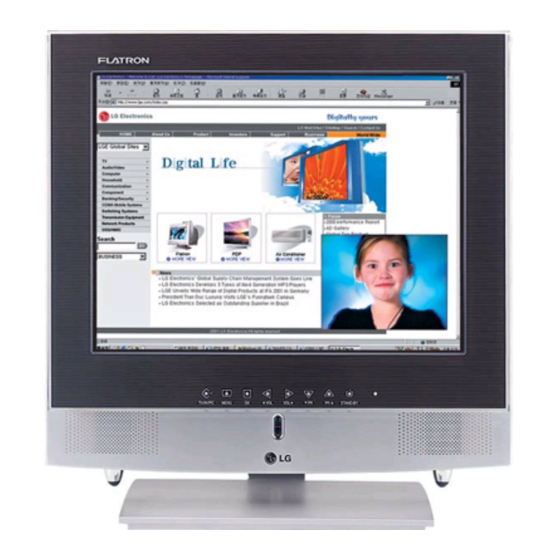
Summary of Contents for LG LN-15A15
- Page 1 All manuals and user guides at all-guides.com website:http://biz.LGservice.com e-mail:http://www.LGEservice.com/techsup.html LCD TV SERVICE MANUAL CHASSIS : ML-012A MODEL : LN-15A15 CAUTION BEFORE SERVICING THE CHASSIS, READ THE SAFETY PRECAUTIONS IN THIS MANUAL.
-
Page 2: Table Of Contents
All manuals and user guides at all-guides.com CONTENTS Contents ....................2 Safety Precautions ..................3 Servicing Precautions ................4 Adjustment Instruction ................6 Troubleshooting ..................12 Exploded View ..................14 Exploded View Parts List ...............15 Replacement Parts List ................ 16 SVC. Sheet .................... -
Page 3: Safety Precautions
All manuals and user guides at all-guides.com SAFETY PRECAUTIONS IMPORT ANT SAFETY NOTICE Many electrical and mechanical parts in this chassis have special safety-related characteristics. These parts are identified by the Schematic Diagram and Replacement Parts List. It is essential that these special safety parts should be replaced with the same components as recommended in this manual to prevent X-RADIATION, Shock, Fire, or other Hazards. -
Page 4: Servicing Precautions
All manuals and user guides at all-guides.com SERVICING PRECAUTIONS CAUTION: Before servicing receivers covered by this service transistors and semicounductor "chip" components. The manual and its supplements and addenda, read and follow the following techniques should be used to help reduce the SAFETY PRECAUTIONS on page 3 of this publication. - Page 5 All manuals and user guides at all-guides.com c. Qulckly move the soldering iron tip to the junction of the Fuse and Conventional Resistor component lead and the printed circuit foil, and hold it Removal/Replacement there only until the solder flows onto and around both the 1.
-
Page 6: Adjustment Instruction
All manuals and user guides at all-guides.com ADJUSTMENT INSTRUCTION 1. Application Object 3. PC Input Mode Adjustment This instruction is for the application to the LCD TV. 3-1. Required Test Equipment (1) A pattern generator being in proportion to 801GF(or VG819) ;... - Page 7 All manuals and user guides at all-guides.com Mode SVGA-75 SVGA-85 XGA-60 XGA-70 XGA-75 MAC-75 XGA-85 H_Total 1056 1048 1344 1328 1312 1152 1376 H_Display 1024 1024 1024 1024 H_Blanking H_Sync H Polarity H_Bp H_Fp H-Freq[KHz] 46.875 53.674 48.363 56.476 60.023 49.725 68.677 /Clk[MHz]...
- Page 8 All manuals and user guides at all-guides.com 4. EDID(The Extended Display Identification Data) EDID Table 0B 0C 0D 0E 5. Option1 data(200PR~A2 ST:1bit,SYS:2bit) OPTION OPTION TEXT I/II SV SCART A2 ST TEXT I/II SV SCART A2 ST 200PR 200PR Data Data - 8 -...
- Page 9 All manuals and user guides at all-guides.com OPTION OPTION TEXT I/II SV SCART A2 ST TEXT I/II SV SCART A2 ST 200PR 200PR Data Data...
- Page 10 All manuals and user guides at all-guides.com OPTION OPTION TEXT I/II SV SCART A2 ST TEXT I/II SV SCART A2 ST 200PR 200PR Data Data...
- Page 11 All manuals and user guides at all-guides.com OPTION TEXT I/II SV SCART A2 ST 200PR Data 6. Option2 data(ACMS~BBACK:1bit,LANG:3bit) OPTION HIDEV ACMS Data 7. Option3 data(IIC AFT~CH+AU:1bit) OPTION MD SAVE MONO CH+AUS IIC AFT Data...
-
Page 12: Troubleshooting
All manuals and user guides at all-guides.com TROUBLESHOOTING 1. General Features Symptom Cause Check Point Button doesn’t 1) Broken components and 1) Check button with eyes function soldering of them Check and repair soldering 2) P2 connector error 2) Check and repair the P2 connector No screen Input error of inverter connector 1) Bend the pin legs of P1 connector ->... - Page 13 All manuals and user guides at all-guides.com MEMO...
-
Page 14: Exploded View
All manuals and user guides at all-guides.com EXPLODED VIEW P801... -
Page 15: Exploded View Parts List
All manuals and user guides at all-guides.com EXPLODED VIEW PARTS LIST PART NO. DESCRIPTION 6304FLP006B LCD,LC151X01-C3P1 LG PHILPS TFT CO 6400VA0017A SPEAKER,GENERAL T401SX-095K14 LG C&D 8 OHM 1.0 4950V00010A METAL,HOLDER SPK SBHG NON 3091V00226R CABINET ASSEMBLY,LN-15A15 ACBLKC ML012A 5020V00360B BUTTON,CONTROL RUBBER SET... -
Page 16: Replacement Parts List
All manuals and user guides at all-guides.com REPLACEMENT PARTS LIST For Capacitor & Resistors, the CC, CX, CK, CN : Ceramic RD : Carbon Film charactors at 2nd and 3rd digit CQ : Polyestor RS : Metal Oxide Film in the P/No. means as follows; CE : Electrolytic RN : Metal Film RUN DATE : 2002.7.2... - Page 17 All manuals and user guides at all-guides.com For Capacitor & Resistors, the CC, CX, CK, CN : Ceramic RD : Carbon Film charactors at 2nd and 3rd digit CQ : Polyestor RS : Metal Oxide Film in the P/No. means as follows; CE : Electrolytic RN : Metal Film RF : Fusible...
- Page 18 TUNER,TAFH-H001P LG NTSC FS. RA930 0RRZVTA001A MNR-14-E0A-J-101 R OHM 100 OH ACCESSORIES RA931 0RRZVTA001A MNR-14-E0A-J-101 R OHM 100 OH 3828VA0308N MANUAL,OWNERS ML012A LN-15A15 LG FILTER & CRYSTAL 6710V00082N REMOTE CONTROLLER,ML012A STEREO 6210TCE001G FILTER,EMC HH-1M3216-501 6410VUH003A POWER CORD,PS204-001 VOLEX UL/CSA 1800MM 6210TCE001G...
- Page 19 All manuals and user guides at all-guides.com July, 200 P/NO : 3828VD0108X Printed in Kore...
- Page 20 All manuals and user guides at all-guides.com...
- Page 21 All manuals and user guides at all-guides.com...
- Page 22 All manuals and user guides at all-guides.com PRINTED CIRCUIT BOARD CONTROL(TOP) WIRING DIAGRAM MAIN(TOP) P902 P201 MAIN1 PWB P601 P602 P001B CONTROL(BOTTOM) BLOCK DIAGRAM MEMORY MEMORY MEMORY MEMORY 5.0V 5.0V LVDS LVDS 8bit 8bit 3.3V IC904 IC904 IC902 IC902 EPROM EPROM SCL/SDA AT27C020...


Need help?
Do you have a question about the LN-15A15 and is the answer not in the manual?
Questions and answers