Advertisement
Table of Contents
1. PWA3* SCREWS
(to attach central power box to floor
panel)
2. TM4* SCREWS
(to mount heaters on sauna walls and
seat panel)
3. KA1* SCREWS
(to attach roof to assembled cabin)
4. KA4* SCREWS
(to attach door handle)
5. Wooden Sauna Sealing
Blocks
6. Auxiliary Cable
7. Far Infrared Heaters
8. Main Control Power Box
9. Wood Door Handle
12
7
4
74.8"
10
190cm
TOOLS & EQUIPMENT
1
4
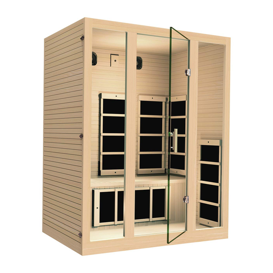
WOOD PANELS DIAGRAM
59.1"
150cm
5
2
9
8
1
Model# MG301HCB/RCB
5
6
39.4"
6
100cm
3
11
2
3
1. Floor Panel
2. Back Bottom Panel
3. Right Bottom Panel
4. Left Bottom Panel
5. Back Top Panel
6. Right Top Panel
7. Left Top Panel
8. Seat Side Panel
9. Seat Top Panel
10. Front Bottom Window/Door Panel
11. Front Top Window/Door Panel
12. Roof Panel (not shown)
7
8
9
Advertisement
Table of Contents

Subscribe to Our Youtube Channel
Related Manuals for JNH MG301HCB


Summary of Contents for JNH MG301HCB
- Page 1 Model# MG301HCB/RCB TOOLS & EQUIPMENT 1. PWA3* SCREWS (to attach central power box to floor panel) 2. TM4* SCREWS (to mount heaters on sauna walls and seat panel) 3. KA1* SCREWS (to attach roof to assembled cabin) 4. KA4* SCREWS (to attach door handle) 5.
- Page 2 ASSEMBLY INSTRUCTIONS STEP 1 STEP 2 STEP 3 STEP 5 STEP 7 STEP 6 STEP 4 STEP 8 STEP 9 STEP 13 STEP 11 STEP 12 STEP 10 STEP 14 STEP 15 STEP 16 STEP 17 STEP 1) First place the bo om panel on the ground. Your sauna should always be placed on a level surface and in a dry area with about 4 feet away from a power outlet.
Need help?
Do you have a question about the MG301HCB and is the answer not in the manual?
Questions and answers