Table of Contents
Advertisement
Quick Links
Advertisement
Table of Contents

Summary of Contents for Link CAN-Lambda
- Page 1 CAN Lambda Module...
-
Page 2: Table Of Contents
Part III Installation 1 Mounting ........................... 7 2 Sensor Placement ........................... 7 3 Wiring ........................... 8 4 Setup w ith Link ECU ........................... 11 Part IV CAN Bus Information 1 CAN Bus Wiring ........................... 13 2 Transmitted Information ........................... 14 3 Received Information ........................... -
Page 3: Part I Welcome
Welcome Welcome CAN-Lambda Module User Manual © 2021 Link Engine Management Ltd... -
Page 4: Part Ii Introduction
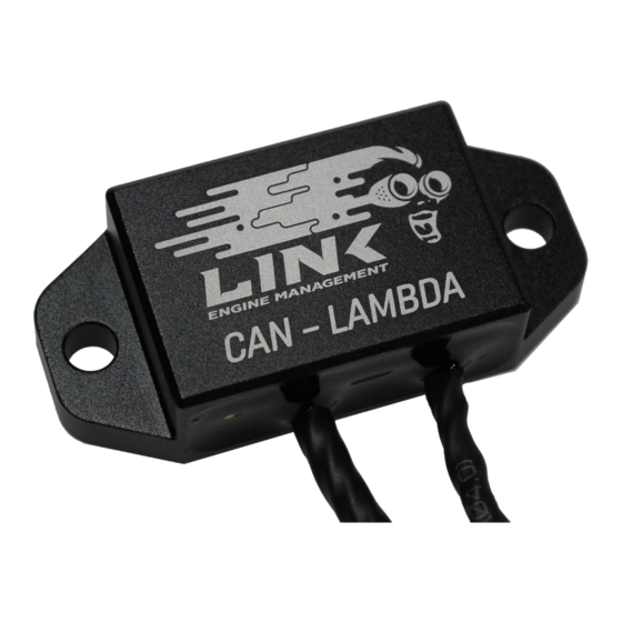
Air fuel ratio information is essential information that all tuners need. The fuel input, power output and air fuel ratio present in the exhaust form the basis of all fuel tuning. Link CAN-Lambda Modules give users a powerful method of adding multiple oxygen sensors and bringing them into the ECU for monitoring or closed-loop lambda control. -
Page 5: Specifications
Operating Temp -20 to 100 °C (-4 to 212 °F) Sensor Genuine Bosch LSU4.9 Sensing Range 0.67 - 10 Lambda Pressure Compensation 0.5 to 2.5 Bar CAN Frequency 1Mbit/s,500kbit/s,250kbit/s,125kbit/s,100kbit/s Connectors Power Loom DTM04-4P mates with DTM06-4S Sensor Loom Bosch LSU4.9 connector © 2021 Link Engine Management Ltd... - Page 6 Link CAN-Lambda Instruction Manual Technical draw ing show ing dim ensions © 2021 Link Engine Management Ltd...
-
Page 7: Part Iii Installation
Installation Installation For best results ensure that all Mounting, Sensor Placement, Wiring and Setup with Link ECU (if applicable) instructions are followed. Mounting Use the mounting holes to secure Link CAN Lambda modules to flat surfaces. Try to keep the CAN Lambda module as far from the heat of the exhaust as possible. -
Page 8: Wiring
Link CAN-Lambda Instruction Manual Wiring Power and Communications Connector Pinout: Description Power CAN L CAN H Front view of connector Sensor Connector Pinout: Description Heater Heater Power Front view of connector © 2021 Link Engine Management Ltd... - Page 9 Installation Wiring: © 2021 Link Engine Management Ltd...
- Page 10 Link CAN-Lambda Instruction Manual © 2021 Link Engine Management Ltd...
-
Page 11: Setup With Link Ecu
The modules must be told which sensor they are connected to (eg cyl 1, cyl 2 etc...) so that they can be identified on the CAN bus. All Link CAN-Lambda modules are shipped pre- configured for a single installation. -
Page 12: Part Iv Can Bus Information
1Mbit/s is not suitable. Up to eight Link CAN-Lambda modules can be used on a CAN bus at any one time. As all Link CAN-Lambda modules are configured to device identifier 0 at the time of manufacture, if more than one module is to be used it/they will need to be configured to have a unique device identifier so it can be recognised on the CAN bus. -
Page 13: Can Bus Wiring
Link distributor to arrange the removal of the internal resistor. Example The following is an example using devices to terminate the bus. Here Link CAN Lambda Modules have been added to the bus. -
Page 14: Transmitted Information
Pump Current · Battery Voltage · Heater Average Voltage When connected to a Link ECU using the built in Link CAN-Lambda CAN communication mode, this information is displayed on the following parameters: · Device identifier 0 (default) · Lambda 1 ·... -
Page 15: Received Information
The Link CAN-Lambda module will wait for two seconds after power up to see if this information is received. If it is not, sensor control will be enabled. IF the information is received, sensor control will not be enabled until engine RPM goes above 400 RPM and disable sensor control when engine speed falls below 10 RPM. - Page 16 Programming a New Device Identifier and Bit Rate To program a new configuration the following information must be sent to the Link CAN-Lambda module. It is OK to send the same information multiple times. Changes will not be applied until next time power is cycled to the Link CAN- Lambda module.
-
Page 17: Part V Diagnostic Information
Diagnostic Information Diagnostic Information When using Link ECU, if using as Lambda 1 (device identifier 0) or Lambda 2 (device identifier 1), internal status and error values will be displayed in PCLink. Otherwise the CAN information will need to be used to determine problems (See Transmitted Information) Lambda output defaults to zero when the module is not able to operate correctly. - Page 18 48 APE over voltage Over 9V. Overheat or pump cell resistance too low Sensor Failure. Check Sensor Overheat or Nernst cell resistance too low Sensor Failure. Contact Link Technical Support 51 - 53 Internal Error © 2021 Link Engine Management Ltd...


Need help?
Do you have a question about the CAN-Lambda and is the answer not in the manual?
Questions and answers