Table of Contents
Advertisement
Advertisement
Table of Contents

Subscribe to Our Youtube Channel
Related Manuals for FoxAlien CNC ROUTER 3018-SE


Summary of Contents for FoxAlien CNC ROUTER 3018-SE
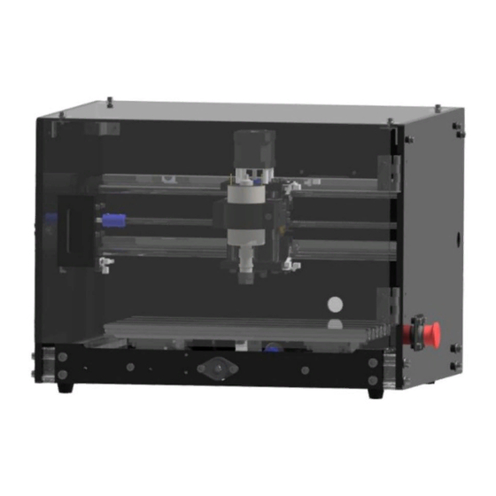
- Page 1 CNC ROUTER 3018-SE USER MANUAL...
-
Page 2: Table Of Contents
Catalog ● I . H a r d w a r e As s e m b l y ● P a r t - 1 X - a x i s S t e p p e r M o t o r A s s e m b l y - - - - - - - - - - - - - - - - - - - - - - - - - - 1 ●... -
Page 3: Part-1 X-Axis Stepper Motor Assembly
I. Hardware Assembly Part-1 X-axis Stepper Motor Assembly Name Picture X-axis Gantry & Spindle Required 42 Stepper Motor Parts M3*12 Bolt Φ3 Gasket Step 1: Assemble the X-axis motor as following pictures. Fix the motor to the left side of the frame with M3*12 bolts and gaskets. -
Page 4: Part-2 Y-Axis Stepper Motor Assembly
I. Hardware Assembly Part-2 Y-axis Stepper Motor Assembly Name Picture Y-axis Base Required 42 Stepper Motor Parts M3*12 Bolt Φ3 Gasket Step 1: Assemble the Y-axis stepper motor as following pictures. Fix the motor to the back of the base with M3*12 bolts and gaskets. -
Page 5: Part-3 Gantry Assembly
I. Hardware Assembly Part-3 Gantry Assembly Name Picture Required M5*14 Bolt Parts Φ5 Gasket Step 1: Fix the gantry right next to the pads on the base with M5*14 bolts and gaskets. -
Page 6: Part-4 Mainboard Assembly
I. Hardware Assembly Part-4 Mainboard Assembly Name Picture Required Parts Mainboard Step 1: Assemble the mainboard to the back of the machine, right next to the side panel. First loosen the T-nuts, insert them to the aluminum profile, and then tighten the screws. -
Page 7: Part-5 Case Assembly-Left Panel
I. Hardware Assembly Part-5 Case Assembly-Left Panel Name Picture Left Acrylic Sheet Required Parts M5*30 Bolt Φ5 Gasket TN5-6-20 Nut Step 1: First connect the left acrylic sheet and pad together via M5*30 bolts. Keep the nuts loose and put them into aluminum profile, and then tighten the nuts. -
Page 8: Part-6 Magnet Suction Block Assembly
I. Hardware Assembly Part-6 Magnet Suction Block Assembly Name Picture Magnet Suction Bracket Required Parts M3*12 Bolt Φ3 Gasket Step 1: Fix the magnet suction block to the left panel with M3*12 bolts and gaskets. -
Page 9: Part-7 Case Assembly-Right Panel
I. Hardware Assembly Part-7 Case Assembly-Right Panel Name Picture Right Acrylic Sheet Required Parts M5*30 Bolt Φ5 Gasket TN5-6-20 Nut Step 1: First connect the right acrylic sheet and pad together via M5*30 bolts. Keep the nuts loose and put them into aluminum profile, and then tighten the nuts. -
Page 10: Part-8 Emergency Stop Switch Assembly
I. Hardware Assembly Part-8 Emergency Stop Switch Assembly Name Picture Required Emergency Stop Switch Parts M4*12 Bolt Step 1: Put the emergency stop switch through the mounting plate. Fix the mounting plate to the right panel with M4*12 bolts. -
Page 11: Part-9 Door Handle Assembly
I. Hardware Assembly Part-9 Door Handle Assembly Name Picture ⑨ Front Acrylic Sheet Required Parts ⑩ Door Handle Step 1: Loosen the screws of the handle’s fixing block, remove the fixing block; Put the door handle into the preserved hole on the acrylic sheet; Fix the door handle to the acrylic sheet with fixing block and screws. -
Page 12: Part - 1 0 C A S E A S S E M B L Y - F R O N T P A N E
I. Hardware Assembly Part-10 Case Assembly-Front Panel Name Picture Front Acrylic Sheet & Door Required 9, 10. Handle Parts M4*8 Flat Head Screw Step 1: Fix the front side acrylic sheet to the hinges with M4*8 screws. -10-... -
Page 13: Part-11 Cooling Fan Assembly
I. Hardware Assembly Part-11 Cooling Fan Assembly Name Picture Cooling Fan Required Parts Back Acrylic Sheet M4*8 Modified Truss Screw Step 1: Use 4pcs M4*8 screws to fix the cooling fan to the back acrylic sheet. -11-... -
Page 14: Part - 1 2 C A S E A S S E M B L Y - B A C K P A N E
I. Hardware Assembly Part-12 Case Assembly- Back Panel Name Picture Back Acrylic Sheet & Cooling Fan 7, 15, 21. & M4*8 Modified Truss Screw Required Parts M5*30 Bolt Φ5 Gasket Step 1: First, to complete the wiring. Shown as following picture, connect the wires to the corresponding ports. - Page 15 I. Hardware Assembly Part-12 Case Assembly- Back Panel Step 2: Fix the acrylic sheet with M5*30 bolts and gaskets. Tighten the bolt through the pad to the base. -13-...
-
Page 16: Part - 1 3 C O R N E R C O N N E C T O R A S S E M B L
I. Hardware Assembly Part-13 Corner Connector Assembly Name Picture Corner Connector Required Parts M4*12 Bolt Φ4 Gasket Step 1: Put the corner connector inside the case, fix it with M4*12 bolts and gaskets from outside. -14-... - Page 17 I. Hardware Assembly Part-14 Case Assembly- Top Panel Name Picture Top Acrylic Sheet Required Parts Corner Connector M4*12 Bolt Φ4 Gasket Step 1: Fix the 4pcs corner connectors to the sides panels, adjust their position to make sure they are leveled.
-
Page 18: Part - 1 4 C A S E A S S E M B L Y - To P P A N E
I. Hardware Assembly Part-14 Case Assembly- Top Panel Assembly finished. -16-... -
Page 19: Part - 1 D R I V E R I N S T A L L A T I O
II. Software & Debugging Part-1 Driver Installation Step 1: Install the driver (Download from U disk) Step 2: To Determine your Machine's COM port • For Windows XP: Right click "My Computer"→ Select "Manage"→ Select "Device Manager". • For Windows 7: Right click "Computer"→ Select "Manage" → Select "Device Manager" from left pane. -
Page 20: Part - 2 D E B U G G I N
II. Software & Debugging Part-2 Debugging Step 1: Open “Grblcontrol” and connect USB unsuccessful successful • Console window prints “[CTRL+X] < Grbl 1.1f [‘$’ for help]” if the connection is successful. • Console window prints “Serial port error 1: No such file or directory” indicates that the connection is failed. - Page 21 II. Software & Debugging Part-2 Debugging Step 2: Enter Step and Feed value, and then click the arrow keys to move X, Y, Z axis. If succeed, the machine is functioning. E.g: Step value=10 means moving distance is 10mm. Feed value=500 means 500mm/min Stop Step 3: Spindle test.
- Page 22 II. Software & Debugging Part-2 Debugging Step 6: Click the direction button to move the bit to the surface of the object. The proper gap between the bit and object’s surface is that only an A4 paper can move through tightly. Click “Zero XY”...
-
Page 23: Part - 3 H O W T O U S E Z - P R O B
II. Software & Debugging Part-3 How to Use Z-Probe Step 1: Measure the thickness of Z-probe. Thickness: 15.04mm Step 2: Modify Z-probe parameter. Default value is Z15, change it to Z15.04 base of the parameter measured in step 1. -21-... - Page 24 II. Software & Debugging Part-3 How to use Z-Probe Step 3: First set the X&Y-axis zero point (follow Part-2, Step 6), and then place the Z-probe. Step 4: Click Z-probe button to start detecting. Step 5: Z-probe detection finished. Remove Z-probe, click “Send” to start engraving. -22-...
- Page 25 This warranty covers the repair or replacement of the broken parts at our discretion. If there is any difficulty during using, feel free to contact us for tech support. E-mail: support@foxalien.com. We will response within 1 business day. Facebook Group Foxalien.com...
Need help?
Do you have a question about the CNC ROUTER 3018-SE and is the answer not in the manual?
Questions and answers