Advertisement
Advertisement
Table of Contents

Related Manuals for FoxAlien LE-4040


Summary of Contents for FoxAlien LE-4040
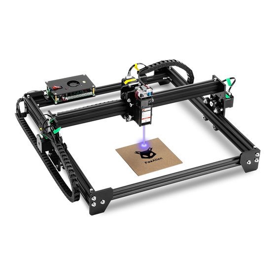
- Page 1 LASER ENGRAVING MACHINE LE-4040 USER MANUAL...
-
Page 2: Part-1 Base Installation
Part-1 Base Installation Name Picture Y-axis Aluminum ① Profile X-axis Aluminum Required ② Profile Parts ⑧ Acrylic Sheet ⑨ Bolt M5*12 Assemble X and Y axis aluminum profiles together as the Step1 picture shown below. Tighten the set screws with hex wrench. Installation Assemble 4pcs acrylic sheets as the picture shown below. - Page 3 Part 2 Gantry Installation Name Picture ③ X-axis Gantry Required Parts ④ Laser Module ⑨ Bolt M5*12 Assemble X-axis Gantry as the picture shown below. Fix it Step1 to Y-axis aluminum profile with 4pcs M5*12 bolts. Installation Steps First loosen the knobs on the laser holder, and then put Step2 the laser module in;...
- Page 4 Part 3 Drag Chain Installation - Y-axis Drag Chain Name Picture Bundled Drag ⑦ Chain(Y-axis) Required Parts ⑨ Bolt M5*8 ⑩ Bolt M4*8 Fix the Y-axis drag chain to the acrylic sheet with 2pcs Installation M4*8 bolts. Step1 Steps Fix the tail to nut pre-installed in the Y-axis aluminum profile with M5*8 bolt.
- Page 5 Part 3 Drag Chain Installation - X-axis Drag Chain Name Picture Bundled Drag ⑦ Chain(X-axis) Required Parts ⑨ Bolt M5*8 ⑩ Bolt M4*8 Fix the X-axis drag chain to the acrylic sheet of X-axis with Installation M4*8 bolt. Step1 Steps Fix the tail to nut pre-installed in the X-axis aluminum profile with M5*8 bolt.
-
Page 6: Part 4 Control Board Installation
Part 4 Control Board Installation Name Picture ⑤ Control Board Required Parts ⑨ Bolt M5*8 Installation Fix the control board to the nut pre-installed in the X-axis Step1 Steps aluminum profile with M5*8 bolts. ⑤ ⑨... - Page 7 Part 5 Wiring - X/ Y-axis & Laser Wiring • Wires are pre-bundled into the drag chain. • Please connect the wires according to the tags after the drag chain is fixed. Y2 wire passes through this hole to connect Motor Y2.
-
Page 8: Control Board Wiring
- Control Board Wiring Laser axis axis Module axis USB Port Power on/off 12V 5A Power Supply Power Indicator Indicator Laser Module... - Page 9 Part 6 Software & Debugging 1. Install the driver (Download from U disk): 2. To Determine your Machine's COM port: • For Windows XP: Right click "My Computer"→ Select "Manage"→ Select "Device Manager". For Windows 7: Right click "Computer"→ Select "Manage" → Select "Device Manager" from left pane.
-
Page 10: Download And Install The Software
3. Download and install the software: 3.1 Click the link to download the free control software: http://lasergrbl.com/ 3.2 Double click to install. 4. Debugging: 4.1 Connect the control board to the PC via USB, select the COM port recognized by the PC. Click the "connect"... - Page 11 4.2 If the connection is successful, console window prints “Grbl 1.1h ['$' for help]”. 4.3 Place wood or other materials under the laser head. Enter “M3 S50” in the command window, and then press Enter. The laser will be turned on with low power. M3: Laser ON S5: Laser output power 50, the minimum and maximum value is 0 ~ 1000 -10-...
- Page 12 4.4 Rotate the lens to focus until the spot is focused to the minimum. 4.5 Enter "M5" in the command window to turn off the laser. M5: Laser OFF 4.6 File → Open File: Open GCODE file or Image format file. -11-...
- Page 13 4.7 Setting parameters, click Next 4.8 Set the Speed and S values. !! Note: Different materials require different engraving speed and S value. You may need to try several times to find appropriate value. -12-...
- Page 14 4.9 Set the zero point and click the button “Run Program” to start engraving. (Machine power-on position is defaulted as the zero point.) 5.0 File->Save Program: Click to save GCODE file. -13-...
-
Page 15: Warranty Terms
Warranty Period. III. This warranty covers the repair or replacement of the broken parts at our discretion. If there is any difficulty during using, feel free to contact us for tech support. E-mail: support@foxalien.com...
Need help?
Do you have a question about the LE-4040 and is the answer not in the manual?
Questions and answers