Table of Contents
Advertisement
Advertisement
Table of Contents

Subscribe to Our Youtube Channel
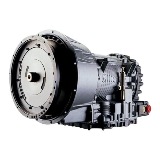
Related Manuals for Allison Transmission 3000


Summary of Contents for Allison Transmission 3000
- Page 1 Mechanic’s Tips 3000 and 4000 Product Families MT3004EN...
- Page 2 Mechanic’s 2006 MARCH Tips MT3004EN Allison Transmission Allison WTEC III Controls (Except 3000 Product Family 7-Speed) 3000 Product Family 4000 Product Family Allison Transmission, Inc. P.O. Box 894 Indianapolis, Indiana 46206-0894 www.allisontransmission.com Printed in USA Copyright © 2007 Allison Transmission, Inc.
- Page 3 NOTES...
-
Page 4: Table Of Contents
TABLE OF CONTENTS SECTION I INTRODUCTION 1–1 ABOUT THIS MANUAL ....... 7 SECTION II PREVENTIVE MAINTENANCE 2–1 PERIODIC INSPECTION AND CARE . - Page 5 SECTION V PREPARING VEHICLE FOR TRANSMISSION INSTALLATION 5–1 ENGINE, TRANSMISSION ADAPTATION REQUIREMENTS ..59 5–2 CHECKING FLEXPLATE DRIVE ASSEMBLY ....62 5–3 CHASSIS AND DRIVELINE INSPECTION .
- Page 6 TRADEMARK USAGE The following trademarks are the property of the companies indicated: • Allison DOC™ is a trademark of General Motors Corporation. • DEXRON ® is a registered trademark of the General Motors Corporation. • TranSynd™ is a trademark of Castrol Ltd. •...
- Page 7 IT IS YOUR RESPONSIBILITY to be completely familiar with the warnings and cautions described in this handbook. It is, however, important to understand that these warnings and cautions are not exhaustive. Allison Transmission could not possibly know, evaluate, and advise the service trade of all conceivable ways in which service might be done or of the possible hazardous consequences of each way.
-
Page 8: Section I Introduction
This handbook is a mechanic’s reference for maintaining, removing, or installing the 3000 and 4000 Product Families on-highway transmission with a WTEC III control system. WTEC III controls were optional on the 3000 and 4000 Product Families on-highway transmission units built in 1997, but became standard on units built starting in 1998. - Page 9 Figure 1–1. 3000 Product Family Transmission with PTO—Cross Section...
- Page 10 Figure 1–2. 3000 Product Family Transmission—Cross Section...
- Page 11 Figure 1–3. 4000 Product Family Transmission with Retarder—Cross Section...
- Page 12 Figure 1–4. 4000 Product Family Transmission with PTO—Cross Section...
- Page 13 Figure 1–5. 4000 Product Family Transmission 7-Speed—Cross Section...
- Page 14 RIGHT-REAR VIEW BREATHER FEEDTHROUGH HARNESS CONNECTOR TORQUE CONVERTER WITH LOCKUP CLUTCH ASSEMBLY PADS AND TORSIONAL DAMPER (BOTH SIDES) MAIN-PRESSURE TAP NOTE: Inch Series Threads PTO PROVISION (AVAILABLE BOTH SIDES) LEFT-FRONT VIEW V07289.02.00 Figure 1–6. 3000 Product Family Transmission with PTO...
- Page 15 TORQUE CONVERTER OUTPUT WITH LOCKUP CLUTCH RETARDER AND TORSIONAL DAMPER TO RETARDER ACCUMULATOR OIL FILL TUBE AND DIPSTICK (AVAILABLE ON BOTH SIDES ) MAIN-PRESSURE TAP NOTE: Inch series threads LEFT-FRONT VIEW V07290.01.00 Figure 1–7. 3000 Product Family Transmission with Retarder...
- Page 16 AND TORSIONAL DAMPER RETARDER TO RETARDER ACCUMULATOR OIL FILL TUBE AND DIPSTICK (AVAILABLE ON MAIN-PRESSURE TAP BOTH SIDES ) NOTE: Inch series threads LEFT-FRONT VIEW V07300.01.00 Figure 1–8. 3000 Product Family Transmission with Retarder and Provisions for Tachograph and Speedometer...
- Page 17 AND TORSIONAL DAMPER RETARDER TO RETARDER ACCUMULATOR OIL FILL TUBE AND DIPSTICK (AVAILABLE ON MAIN-PRESSURE TAP BOTH SIDES ) NOTE: Inch series threads LEFT-FRONT VIEW V07401.02.00 Figure 1–9. 3000 Product Family Transmission with Retarder and Provisions for Tachograph and Sump Cooler...
- Page 18 (TOP RIGHT POSITION) SHIPPING BRACKET (3) FEEDTHROUGH HARNESS CONNECTOR MOUNTING ENGINE SPEED SENSOR TURBINE SPEED SENSOR OUTPUT SPEED SENSOR FILL TUBE NAMEPLATE COOLER PORTS RIGHT-REAR VIEW MOUNTING PAD (BOTH SIDES) FEEDTHROUGH HARNESS CONNECTOR (BOTTOM LEFT POSITION) COOLER PORTS MAIN-PRESSURE TAP LEFT-REAR VIEW V07291.00.01 Figure 1–10.
- Page 19 RETARDER PTO (TOP RIGHT POSITION) FEEDTHROUGH MOUNTING PADS HARNESS (BOTH SIDES) CONNECTOR NAMEPLATE FILL TUBE TURBINE SPEED SENSOR ENGINE SPEED SENSOR RIGHT-FRONT VIEW MOUNTING PADS (BOTH SIDES) PTO (TOP RIGHT POSITION) FEEDTHROUGH HARNESS CONNECTOR RETARDER SUMP COOLER PROVISION PTO (BOTTOM LEFT POSITION) MAIN-PRESSURE TAP COOLER PORTS...
- Page 20 MOUNTING PADS (BOTH SIDES) PTO (TOP RIGHT POSITION) FEEDTHROUGH HARNESS CONNECTOR C6 ADAPTER HOUSING REAR COVER PTO (BOTTOM LEFT POSITION) MAIN-PRESSURE TAP LEFT-REAR MOUNTING PADS (BOTH SIDES) PTO (TOP RIGHT POSITION) C6 ADAPTER HOUSING RETARDER PTO (BOTTOM LEFT SUMP POSITION) COOLER PROVISION MAIN-PRESSURE TAP...
-
Page 21: Section Ii Preventive Maintenance
PREVENTIVE Section II MAINTENANCE 2–1. PERIODIC INSPECTION AND CARE Clean and inspect the exterior of the transmission at regular intervals. Severity of service and operating conditions determine the frequency of these inspections. Inspect the transmission for: • Loose bolts—transmission and mounting components •... -
Page 22: Transmission Fluid Test
If the level is too high, the fluid aerates—causing the transmission to shift erratically and overheat. Fluid may be expelled through the breather or dipstick tube when the fluid level is too high. 2–3. TRANSMISSION FLUID TEST a. Electronic Fluid Test Procedure. Fluid level can be electronically displayed on a pushbutton (non-strip type) shift selector, lever shift selector, or Allison DOC™... - Page 23 HOLD OVERRIDE BUTTON MODE INDICATOR (LED) MODE MODE MODE BUTTON MODE ID DIGITAL DISPLAY DISPLAY MODE/ DIAGNOSTIC BUTTON SIX-SPEED, LEFT-HAND SIX-SPEED, RIGHT-HAND LEVER SELECTOR LEVER SELECTOR DIGITAL DISPLAY MODE ID MODE INDICATOR (LED) MODE Push simultaneously 3 D N R to enter diagnostic mode and fluid level check (optional)
- Page 24 L – 9 5 Sensor failure NOTE: Report sensor failure to a distributor or dealer in your area. Consult the telephone directory for the Allison Transmission distributor or dealer near you. The countdown is restarted when the condition causing the “invalid for display”...
- Page 25 Allison DOC™ Message — SUMP TEMP HI — OUTPUT SPEED HI — CHECK CODES • Exiting the Fluid Level Mode. Exit as follows: — For a pushbutton shift selector, press the N (Neutral) pushbutton once. — For a lever selector, press the DISPLAY MODE/DIAGNOSTIC button once or move the lever to a range position.
- Page 26 4. With the engine running, remove the dipstick from the tube and wipe the dipstick clean. 5. Insert the dipstick into the tube until it stops and then remove. Read the fluid level. Repeat the test procedure to verify the reading. 6.
- Page 27 NOTE: Calibrate level marking locations with respect to transmission control module split line and fill tube. Scale none. *Dimension determined by installation. **Reference dimension only. Actual dimension to be determined by installation. ***Reference drawing AS66-460. ****Reference drawing AS67-460. V07301.00.05 Figure 2–2. Standard 3000 And 4000 Product Families Dipstick Markings...
-
Page 28: Keeping Fluid Clean
fluid is qualified for use in Allison transmissions, look for fluid license or approval numbers on the container, or consult the lubricant manufacturer. Consult your Allison Transmission dealer or distributor before using other fluid types. CAUTION: Disregarding minimum fluid temperature limits can result in transmission malfunction or reduced transmission life. -
Page 29: Transmission Fluid And Filter Change Intervals
Table 2–4. Transmission Fluid Operating Temperature Requirements (cont’d) Ambient Temperature Below Which Preheat is Required Viscosity Grade Celsius Fahrenheit SAE 15W–40 –15 SAE 30W SAE 40W * “Arctic” as defined by MIL-L-46167B (Ref. SIL 13-TR-90) 2–6. TRANSMISSION FLUID AND FILTER CHANGE INTERVALS a. -
Page 33: Transmission Fluid Contamination
If detected, change transmission fluid * Any fluid not included on the Allison Approved Fluid List. The Approved Fluids Lists may be found at the Allison Transmission website, www.allisontransmission.com. b. Monitoring Wear. Absolute maximum values cannot be applied to wear metals of an automatic transmission due to the many variables present that affect concentration limits. - Page 34 considered a trendline. Cause for concern should only occur when significant deviations in the established trendline are present. While trendline analysis on wear metals can prove informative and useful, a transmission removal decision should not be based solely upon the analysis. A removal based solely on wear metal analysis may result in an unnecessary tear down.
- Page 35 • Appearance of fluid (presence of water causes a cloudy or gray, pink, or strawberry colored fluid) • Steam from the breather. For additional field analysis information, refer to Allison Transmission publication number GN2055EN, Automatic Transmission Fluid Technician’s Guide. Use this publication to review testing methods and limits of water/glycol content.
-
Page 36: Transmission Fluid And Filter Change Procedure
CONTAMINATION, Paragraph a. Fluid Examination. b. Replace Filters. Refer to Figure 2–3. For 3000 Product Family before S/N 6510069120: 1. Remove twelve bolts 1, two filter covers 2, two O-rings 5, two square-cut seals 4, and two filters 6 from the bottom of the control module. - Page 37 PLUG V03532.02.02 Figure 2–3. Location of Filters for Service For 3000 Product Family beginning with S/N 6510069120 and 4000 Product Family beginning with S/N 6610009730: 1. Remove twelve bolts 1, two filter covers 2, two gaskets 3, two O-rings 4, two O-rings 5 and two filters 6 from the bottom of the control module.
-
Page 38: Fluid Leak Diagnosis
Transmission Sump Liters Quarts Liters Quarts 4 inch 3000 Product Family 2 inch 4 inch † 4000 Product Family 2 inch† * Approximate quantities, do not include external lines and cooler hose. † Add 2.8 liters (3 quarts) for transmissions with PTO. - Page 39 • Transmission mating surfaces: — Attaching bolts not correctly aligned — Improperly installed or damaged gasket — Mating surface(s) damaged • Housing leak: — Fill tube or plug seal damaged or missing — Fill tube bracket dislocated — Oil cooler connector fittings loose or damaged —...
- Page 40 4. Visually inspect the suspected area and trace the leak path over the white powder. c. Black light and Dye Method. A dye and black light kit for finding leaks is available. Refer to the manufacturer’s directions when using the kit. Refer to the kit directions for the color of the fluid/dye mix.
-
Page 41: Breather
2–10. BREATHER a. Location and Purpose. The breather is located on top of the transmission converter housing. The breather prevents air pressure build-up within the transmission and its passage must be kept clean and open. b. Maintenance. CAUTION: DO NOT SPRAY STEAM, WATER, OR CLEANING SOLUTION DIRECTLY AT THE BREATHER. - Page 42 Whenever the CHECK TRANS light is illuminated, the ECU logs a diagnostic code in memory. The diagnostic codes can be accessed through the shift selector display or through the Allison DOC™ service tool. NOTE: Diagnostic codes can be logged without illuminating the CHECK TRANS light.
- Page 43 Table 2–11. Diagnostic Code Display Code List Position Main Code Subcode When using the shift selector to retrieve trouble codes, if the mode indicator (LED) is illuminated the displayed code is active. If the mode indicator is not illuminated the displayed code is inactive. In normal operating mode, an illuminated mode indicator signifies secondary mode operation.
- Page 44 d. Retrieving Troubleshooting Codes. NOTE: Strip Pushbutton Shift Selectors cannot display or clear diagnostic codes. After road testing the vehicle, determine if any diagnostic codes have set. Retrieve the codes by using the shift selector. Refer to Figure 2–4. • Enter diagnostic mode. •...
- Page 45 HOLD OVERRIDE BUTTON MODE INDICATOR (LED) MODE MODE MODE BUTTON MODE ID DIGITAL DISPLAY DISPLAY MODE/ DIAGNOSTIC BUTTON SIX-SPEED, LEFT-HAND SIX-SPEED, RIGHT-HAND LEVER SELECTOR LEVER SELECTOR DIGITAL DISPLAY MODE ID MODE INDICATOR (LED) MODE Push simultaneously 3 D N R to enter diagnostic mode and fluid level check (optional)
-
Page 46: Transmission Stall Test And Neutral Cool-Down Check
To help locate intermittents, it sometimes helps to place the appropriate tester on the suspected component or circuit and simulate operating conditions—wiggle, pull, bump, and bend while watching the tester. g. Exiting Diagnostic Mode. NOTE: Strip Pushbutton Shift Selectors cannot display or clear diagnostic codes. - Page 47 1. The manufacturer concurs with performing a full-throttle transmission stall test. 2. The engine programmable parameter for 0 rpm transmission output speed is set higher than the value expected at transmission stall speed. 3. The vehicle is in an area in which a transmission stall test can be safely performed.
- Page 48 c. Performing a Transmission Stall Test. 1. Start the engine. While in neutral let the transmission warm to normal operating temperature: — Sump temperature 71–93°C (160–200°F) — Converter out temperature 82–104°C (180–220°F) 2. Determine the hot transmission fluid level and adjust as necessary. 3.
- Page 49 d. Driving Transmission Stall Test. NOTE: If the vehicle is equipped with a smoke controlled or an emission controlled engine or engine control programming inhibiting engine acceleration, the following stall test procedure can be used. WARNING: To help avoid personal injury and/or equipment damage, a driving transmission stall test must be performed by a trained driver and a qualified technician.
- Page 50 f. Performing A Driving Transmission Stall Test. CAUTION: The transmission stall test procedure causes a rapid rise in transmission fluid temperature that can damage the transmission. Never maintain a stall condition once engine speed stabilizes or converter out (to cooler) temperature exceeds 150°C (300°F). During a stall condition, converter out temperature rises much faster than the internal (sump) temperature.
- Page 51 h. Transmission Stall Test Results. NOTE: Environmental conditions, such as ambient temperature, altitude, engine accessory loss variations, etc., affect the power input to the converter. Due to such conditions, stall speed can vary from specification by ±150 rpm and still be accepted as within published stall speed.
-
Page 52: Section Iii Removing Transmission
Position the wiring harness so it does not interfere with transmission removal. — For the 3000 Product Family transmissions, disconnect the input (engine) and output speed sensors. — For the 4000 Product Family transmissions, disconnect the input... -
Page 53: Uncoupling From Driveline, Engine, And Vehicle
3. If a retarder is used, disconnect the retarder accumulator hydraulic line from the retarder. Disconnect any cooling lines. — For 3000 Product Family transmissions built before January, 1998, disconnect the transmission external harness from the retarder connector. If used, disconnect the tachograph or speedometer cable from the port on the rear of the retarder housing —... -
Page 54: Removing The Transmission
M10 x 1.5 x 30 bolts. Output flanges or yokes are now retained by one M14 x 2.0 x 70 bolt. For the 3000 Product Family, the one-bolt design began at S/N 6510184819. For the 4000 Product Family, the one-bolt design began at S/N 6610038064. - Page 55 BREATHER ASSEMBLY PADS TACHOGRAPH ENGINE SPEED SENSOR FEEDTHROUGH HARNESS CONNECTOR TO COOLER NAMEPLATE NOTE: Inch Series Threads RETARDER CONNECTOR FROM COOLER TEMPERATURE SENSOR NOTE: Inch Series Threads SPEED SENSOR V07359 Figure 3–2. 3000 Product Family Transmissions Disconnect Locations...
-
Page 56: Section Iv Transmission Preparation
TRANSMISSION Section IV PREPARATION 4–1. INSPECTING INPUT COMPONENTS a. Bolt Holes. Inspect all bolt holes on the front of the transmission and rear of the engine that are used in connecting the transmission to the engine. The threads must be undamaged and the holes free of chips or foreign material. b. -
Page 57: Installing Pto
O-ring over the threads of each bolt, so that the O-ring seats against the retainer plug. Install retainer plug and bolts into the flange or yoke. — Tighten bolts to 30–35 N•m (22–26 lb ft) for a 3000 Product Family transmission. -
Page 58: Installing Fill Tube And Seal
(38–45 lb ft). 4–4. INSTALLING FILL TUBE AND SEAL a. Location. • The 3000 Product Family fill tube may be mounted on either the right or left side. The unused fill tube provision must have a plug to fill the tube opening. -
Page 59: Inspecting Plugs And Openings
4–5. INSPECTING PLUGS AND OPENINGS Carefully inspect all sides and the bottom of the transmission for loose or missing plugs. a. Pressure Plugs. Determine if 0.4375–20 UNF-2A pressure plugs are tightened to 10–13 N•m (7–10 lb ft). b. Fluid Drain Plug. Determine that the drain plug is tightened to 25–32 N•m (18–24 lb ft). -
Page 60: Section V Preparing Vehicle For Transmission Installation
• 0–150 mm (0–6 inch) depth micrometer b. Flywheel Housing Pilot Bore Diameter. The flywheel housing pilot bore diameter must measure: • 3000 Product Family—447.68–447.81 mm (17.625–17.630 inches). • 4000 Product Family—511.18–511.30 mm (20.125–20.130 inches). c. Flywheel Housing Bore Runout. Flywheel housing bore runout cannot exceed 0.51 mm (0.020 inch) TIR. - Page 61 Figure 5–1. 3000 Product Family Engine Adaptation...
- Page 62 Figure 5–2. 4000 Product Family Engine Adaptation...
-
Page 63: Checking Flexplate Drive Assembly
Flexplate Bolt Hole Flatness. Flexplate flatness in the area of the bolt holes is not a measurement required for the 3000 and 4000 Product Families transmissions. i. Torque Converter Axial Location. Using a depth gauge, measure from the face of the torque converter housing to the torque converter flexplate adapter mounting face. -
Page 64: Chassis And Driveline Inspection
CRANKSHAFT HUB ADAPTER STARTER RING GEAR WEAR PLATE ENGINE FLYWHEEL HOUSING FLEXPLATE ASSEMBLY FLEXPLATE ADAPTER TRANSMISSION V00533..00.04 Figure 5–4. Arrangement of Adaptation Components 5–3. CHASSIS AND DRIVELINE INSPECTION Inspect the chassis and driveline components for the following conditions, and correct them as appropriate. •... -
Page 65: Cooler, Filter, And Lines
• Universal joints: — freedom of movement — damaged or worn-out — correctly lubricated — correctly indexed • Vehicle differential backlash—manufacturer’s specification • Universal joint coupling—alignment and differential damage • Cross-frame members and rear support members—condition and location • PTO-driven equipment shafts and couplings—damaged or misaligned •... -
Page 66: Inspecting Controls
5–5. INSPECTING CONTROLS a. Inspection. Inspect the following and correct any faulty conditions: • Shift selector: — improper operation — poor electrical connections — improper harness routing • Cab and chassis wiring harness: — poor electrical connections — frayed insulation —... - Page 67 TPS should not need adjustment. If TPS adjustment is necessary, confirm that it has been installed to Allison Transmission specification (refer to Figure 5–5). The TPS is self-calibrating and therefore has no optimum closed throttle or full throttle count value.
- Page 68 BENDING LOAD APPLIED UNACCEPTABLE INSTALLATION MOUNTING PROVISION: Use M6 x 1.00 or ⁄ -20 in. series bolts 3 places 10.0° MAX INSTALLED Torque M6 x 1.00 bolt to 10–13 N•m (84–120 lb in.) OPERATING ANGLE Torque ⁄ -20 in. series bolts to 13–14 N•m (108–132 lb in.) IN ALL DIRECTIONS Mount to a solid frame member.
- Page 69 2. Secure the sensor body using the mounting holes provided. 3. Install a heat shield if any part of the throttle sensor is near the exhaust manifold, turbochargers, or any other heat source. • Adjust the throttle sensor as follows: 1.
-
Page 70: Section Vi Installing Transmission Into Vehicle
INSTALLING TRANSMISSION INTO Section VI VEHICLE 6–1. HANDLING a. Preventing Damage. Handle the transmission carefully to prevent damage to components in the installation path. b. Control of Transmission Movements. Use a hoist or transmission jack that allows precise control of transmission movements during installation. 6–2. -
Page 71: Installing Transmission Mounting Components
(38–45 lb ft) or -14 bolts tightened to 73–88 N•m (54–65 lb ft) or -16 bolts tightened to 49–58 N•m (36–43 lb ft). 9. Remove the flexplate guide bolt through the engine flywheel housing access opening. Replace it with a self-locking bolt. Tighten the bolt finger tight. NOTE: DO NOT tighten any flexplate-to-flexplate adapter bolts until all of the bolts have been installed and tightened finger tight. -
Page 72: Connecting Power Takeoff Controls
0.9 m (3 ft). CONTROLS on T200/T300 installations). V07302.00.02 Figure 6–1. 3000 And 4000 Product Families Output Retarder Accumulator Installation NOTE: Be sure a pressure protection valve is correctly installed between the vehicle brake air system and the accumulator control solenoid. -
Page 73: Connecting Parking Brake Control
Refer to Figure 6–2 for typical cooler port locations on the transmission and recommended torque for cooler line fittings. 6–9. CONNECTING ELECTRICAL COMPONENTS NOTE: Allison Transmission electronic control systems are designed and manufactured to comply with all FCC and other guidelines regarding radio frequency interference/electromagnetic interference (RFI/EMI) for transportation electronics. - Page 74 4000 PRODUCT FAMILY 3000 PRODUCT FAMILY COOLER COOLER RETURN RETURN COOLER COOLER TORQUE 54–68 N•m (40–50 lb ft) TORQUE 54–68 N•m (40–50 lb ft) REAR VIEW REAR VIEW COOLER COOLER RETURN COOLER RETURN COOLER TORQUE 54–68 N•m (40–50 lb ft) TORQUE 34–47 N•m (25–35 lb ft)
-
Page 75: Connecting Speedometer Drive
For the 3000 Product Family connect: engine and output speed sensors, and the retarder control connector (if retarder is present and unit was built before January, 1998) c. For 3000 Product Family units with retarder built beginning January, 1998 connect: the retarder temperature thermistor, the output speed sensor, and the retarder valve body connector. -
Page 76: Filling Hydraulic System
6–11. FILLING HYDRAULIC SYSTEM 1. Select a transmission fluid—refer to Section 2–5, FLUID RECOMMENDATIONS. 2. Fill the transmission with the required amount of fluid—refer to Table 2–9. 3. Run the engine for about one minute and check the fluid level—refer to Section 2–3, TRANSMISSION FLUID TEST, Paragraph c, Cold Test Procedure. -
Page 77: Section Vii Inspections And Adjustments
— Expansion plug (prior to April 1997)—1–2 N•m (9–18 lb inch) — Flexplate adapter-to-converter cover bolts—33–39 N•m (25–29 lb ft) — Output flange bolt(s): 3000 Product Family transmission—30–35 N•m (22–26 lb ft) 4000 Product Family transmission—51–61 N•m (38–45 lb ft) 3000 and 4000 Product Families Transmissions built after December 1, 1998—70–80 N•m (52–59 lb ft) - Page 78 — TPS to transmission bracket M6 bolts—10–13 N•m (84–120 lb inch); -20 bolts—12–15 N•m (108–132 lb inch) • Cooler Fluid Lines and Air Hose for: — No leaks — Connection tightness — Correct routing • Throttle sensor for: — Proper adjustment —...
-
Page 79: Road Test And Vehicle Operation Inspection List
• Troubleshoot—if codes exist after the road test, problems must be found and corrected (refer to TS2973EN, WTEC III Troubleshooting Manual). b. Service and Maintenance. Refer to the current issue of the 3000 and 4000 Product Families service manuals for detailed transmission service and maintenance instructions. - Page 80 c. Road Test Inspection List. Complete the following checklist. • Neutral Start Circuit: — Starts only in neutral • Instruments: — CHECK TRANS light and shift selector display — Transmission fluid pressure gauge—if used — Speedometer — Temperature gauge—if used —...
-
Page 81: Section Viii Customer Service
8–1. OWNER ASSISTANCE There are distributors and dealers around the world ready to stand behind every Allison Transmission product. Any situation that arises in connection with the sale, operation, or service of your transmission will be handled by the distributor or dealer in your area. - Page 82 Table 8–1. Available Service Literature 3000 Product 3000 Product Family 4000 Product Transmission Model Family 7–Speed Family Allison DOC™ User GN3433EN GN3433EN GN3433EN Guide Automatic Transmission GN2055EN GN2055EN GN2055EN Fluid Technician’s Guide Job-Aid Cards JA3426EN JA3426EN JA3427EN Operator’s Manual* OM2995EN...
- Page 83 MT3004EN 200603 www.allisontransmission.com Printed in USA 200701...
Need help?
Do you have a question about the 3000 and is the answer not in the manual?
Questions and answers