Table of Contents
Advertisement
Quick Links
- 1 A Brief Description of the Allison 3000 Mh, 4000 Mh Series Transmissions
- 2 Pushbutton Shift Selector
- 3 Fluid Level Check Using the Pushbutton or Lever Shift Selector
- 4 Recommended Automatic Transmission Fluid and Viscosity Grade
- 5 Fluid and Internal Filter Change Interval Recommendations
- 6 Transmission Fluid and Filter Change Procedure
- Download this manual
Advertisement
Table of Contents

Related Manuals for Allison Transmission 3000 MH Series


Summary of Contents for Allison Transmission 3000 MH Series
- Page 1 OWNER’S MANUAL ALLISON 3000 MH 4000 MH...
- Page 2 OM3349EN Owner’s Manual Allison On-Highway 3000 MH, 4000 MH Series Transmissions (WTEC III Controls) 3000 MH, MHR, MHP, MHPR 4000 MH, MHR, MHP, MHPR Division of General Motors Corporation MARCH 2000 P.O. Box 894 Indianapolis, Indiana 46206-0894 Printed in U.S.A. Copyright ©...
-
Page 3: Warnings, Cautions, And Notes
IT IS YOUR RESPONSIBILITY to be completely familiar with the warnings and cautions described in this handbook. It is, however, important to understand that these warnings and cautions are not exhaustive. Allison Transmission could not possibly know, evaluate, and advise the service trade of all conceivable ways in which service might be done or of the possible hazardous consequences of each way. -
Page 4: Table Of Contents
TABLE OF CONTENTS Page Warnings, Cautions, and Notes........INTRODUCTION Keeping That Allison Advantage . - Page 5 Service Literature ..........Allison Transmission Distributors ........
-
Page 6: Introduction
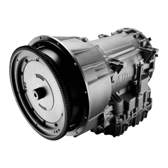
INTRODUCTION S E R I E S KEEPING THAT ALLISON ADVANTAGE STOP SPEED Y I E L D ZONE HILL V01724 Allison MH Series transmissions provide many advantages for the driver who must “stop and go” or change speeds frequently. Driving is easier, safer, and more efficient. - Page 7 NOTE: Inch Series Threads BREATHER FEEDTHROUGH HARNESS TORQUE CONVERTER CONNECTOR WITH LOCKUP CLUTCH AND TORSIONAL DAMPER ASSEMBLY PADS (BOTH SIDES) FILL TUBE AND DIPSTICK (Available on both sides) MAIN-PRESSURE TAP NOTE: Inch Series Threads V06341 Typical 3000 MH Series Transmission...
- Page 8 BREATHER FEEDTHROUGH HARNESS CONNECTOR MOUNTING INPUT SPEED SENSOR TURBINE SPEED SENSOR OUTPUT SPEED SENSOR FILL TUBE AND DIPSTICK NAMEPLATE COOLER PORTS BREATHER MOUNTING PAD (BOTH SIDES) FEEDTHROUGH HARNESS CONNECTOR COOLER PORTS MAIN-PRESSURE TAP V06342 Typical 4000 MH Series Transmission...
-
Page 9: A Brief Description Of The Allison 3000 Mh, 4000 Mh Series Transmissions
Oil Level Sensor (OLS) Present, Not Present Throttle Analog, J 1587, J 1939 Engine Coolant Temperature Analog, J 1939, J 1587 Seek help from your nearest Allison Transmission service outlet when any of the above items are present, but are not responding properly. -
Page 10: Torque Converter
Another feature of the 3000 MH and 4000 MH Series transmission is its ability to adapt or “learn” as it operates. Each shift is measured electronically, stored and used by the ECU to adapt or “learn” the optimum conditions for future shifts. NOTE: If the shift quality of low mileage vehicles, or vehicles with new or recalibrated ECUs is unacceptable, follow the procedure explained in the ADAPTING SHIFTS section. -
Page 13: Planetary Gears And Clutches
PLANETARY GEARS AND CLUTCHES A series of three helical planetary gear sets and shafts provides the mechanical gear ratios and direction of travel for the vehicle. The planetary gear sets are controlled by five multiplate clutches that work in pairs to produce six forward speeds and one reverse speed. -
Page 14: Shift Selectors
SHIFT SELECTORS S E R I E S DESCRIPTION OF AVAILABLE TYPES HOLD OVERRIDE BUTTON MODE INDICATOR (LED) MODE MODE MODE BUTTON MODE ID ✽ DIGITAL DISPLAY DISPLAY MODE/ DIAGNOSTIC BUTTON SIX-SPEED, LEFT-HAND SIX-SPEED, RIGHT-HAND LEVER SELECTOR LEVER SELECTOR ✽ DIGITAL DISPLAY MODE ID MODE... -
Page 15: Lever Shift Selector
With an Allison-equipped vehicle, it is not necessary to select the right moment to upshift or downshift during changing road and traffic conditions. The Allison MH Series does it for you. However, knowledge of the shift selector positions, ranges available, and when to select them, will make vehicle control even easier. It is recommended to select lower ranges when descending long grades (with and without retarder) to reduce wear on service brakes. -
Page 16: Pushbutton Shift Selector
the digital display are illuminated for more than 12 seconds, the ECU did not complete initialization. When the digital display is blank, there is no power to the selector. When the display shows a “ ” (cateye), a selector-related fault code has been logged. -
Page 17: Range Selection - Pushbutton And Lever Shift Selectors With Digital Display
RANGE SELECTION — PUSHBUTTON AND LEVER SHIFT SELECTORS WITH DIGITAL DISPLAY RANGE MODE SELECTION MODE TYPICAL PUSHBUTTON LEVER SELECTOR SELECTOR V03497.01 WARNING: If you leave the vehicle and the engine is running, the vehicle can move suddenly and you or others could be injured. If you must leave the engine running, do not leave the vehicle until you: •... - Page 18 RANGE SELECTION — PUSHBUTTON AND LEVER SHIFT SELECTORS WITH DIGITAL DISPLAY (cont’d) RANGE MODE SELECTION MODE TYPICAL PUSHBUTTON LEVER SELECTOR SELECTOR V03497.01 WARNING: When starting the engine, make sure the service brakes are applied. Failure to apply the service brakes may result in unexpected vehicle movement.
- Page 19 RANGE SELECTION — PUSHBUTTON AND LEVER SHIFT SELECTORS WITH DIGITAL DISPLAY (cont’d) RANGE MODE SELECTION MODE TYPICAL PUSHBUTTON LEVER SELECTOR SELECTOR V03497.01 WARNING: Even though D (Drive) is selected, it may not be obtained due to an active inhibitor. Always be sure that “D” is not flashing whenever D (Drive) is selected.
- Page 20 RANGE SELECTION — PUSHBUTTON AND LEVER SHIFT SELECTORS WITH DIGITAL DISPLAY (cont’d) RANGE MODE SELECTION MODE TYPICAL PUSHBUTTON LEVER SELECTOR SELECTOR V03497.01 WARNING: If you just downshift or just use service brakes when going downhill, you can lose control and cause injury and property damage.
-
Page 21: Driving Tips
DRIVING TIPS S E R I E S CHECK TRANS LIGHT The electronic control system is programmed to inform the operator of a problem with the transmission system and automatically take action to protect the operator, vehicle, and transmission. When the Electronic Control Unit (ECU) detects a problem condition, the ECU restricts shifting, turns on the CHECK TRANS light on the instrument panel, and registers a diagnostic code. -
Page 22: Diagnostic Codes
Generally, while the CHECK TRANS light is on, upshifts and downshifts will be restricted and direction changes will not occur. Lever and pushbutton shift selectors do not respond to any operator shift requests while the CHECK TRANS light is illuminated. The lockup clutch is disengaged when transmission shifting is restricted or during any critical transmission malfunction. -
Page 23: Using The Engine To Slow The Vehicle
Manual range downshifts will not occur until a calibration value of output speed is reached. When a range downshift is manually selected and the transmission output speed is above the calibration value, the transmission will stay in the range it was in even though a lower range was requested. -
Page 24: Using The Hydraulic Retarder
to slow the vehicle. When a lower speed is reached, the ECU will automatically down-shift the transmission. Engine braking provides good speed control for going down grades. When the vehicle is heavily loaded, or the grade is steep, it may be desirable to preselect a lower range before reaching the grade. - Page 25 WARNING: If your transmission has a retarder but it is not functioning, it may not have been “autodetected” during vehicle manufacture. Go immediately to your nearest Allison Transmission service outlet to have “autodetect” reset or the retarder enabled using ®...
-
Page 26: Range Preselection
Contact your vehicle manufacturer to understand how the retarder controls have been integrated into your vehicle. CAUTION: Observe the following cautions when driving a vehicle equipped with a retarder. THE RETARDER WORKS ONLY WHEN THE ENGINE IS AT CLOSED THROTTLE. OBSERVE TRANSMISSION AND ENGINE TEMPERATURE LIMITS AT ALL TIMES. - Page 27 Adaptive does not function below 100 degrees Fahrenheit transmission sump temperature. Normal running hot sump temperature is recommended before this procedure is followed. Check transmission sump level and assure it is set to “Hot Full” at normal running hot sump temperature before this procedure is followed. All segments of this procedure are to be repeated a minimum of 5 times or until shift quality variation is indistinguishable from shift to shift.
-
Page 28: Cold Weather Starts
Release the throttle to Closed and, using Light vehicle brakes and the retarder or engine brake, decelerate vehicle to a stop. NOTE: Allison Transmission does not recommend using the vehicle brakes to “force” Powered Downshifts (PD, downshifts with the throttle applied). -
Page 29: Driving On Snow Or Ice
DRIVING ON SNOW OR ICE WARNING: Using the retarder on wet or slippery roads can be like jamming on the brakes — your vehicle may slide out of control. To help avoid injury or property damage, turn the retarder enable to OFF when driving on wet or slippery roads. -
Page 30: High Fluid Temperature
and apply a steady, light throttle and allow the vehicle to rock in R (Reverse) as far as it will go. Again, apply and hold the service brakes and allow the engine to return to idle. This procedure may be repeated in D (Drive) and R (Reverse) if each directional shift continues to move the vehicle a greater distance. -
Page 31: Parking Brake
PARKING BRAKE Select N (Neutral) and be sure that the parking brake is applied to secure the vehicle when it is not attended. Always make sure the vehicle’s parking brake system has been maintained per the manufacturer’s specifications. WARNING: Take the following precautions so that unexpected, possible sudden vehicle movement is avoided. -
Page 32: Power Takeoff Operation
If a PTO is present, it will be mounted on either left side, right side, or top for a 3000 MH Series transmission depending upon the converter housing configuration. The PTO is located on the left side or top for a 4000 MH Series transmission. The PTO drive gear is engine-driven and therefore provides direct engine power. -
Page 33: Care And Maintenance
Help the WTEC III control system oversee the operation of the transmission. Minor problems can be kept from becoming major problems if you notify an Allison Transmission distributor or dealer when one of these conditions occur: • Shifting feels odd •... -
Page 34: Fluid Level Check Using The Pushbutton Or Lever Shift Selector
transmission is known to contain an OLS. If an OLS is not detected during the first 49 engine starts, the WTEC III system concludes that no OLS is present. If an OLS is known to be present, but has not been detected, then troubleshooting of the OLS circuit is required. - Page 35 • To exit the fluid level display mode, press any range button on the pushbutton shift selector, or press the display mode button once on the lever shift selector. * Report sensor failure display to a distributor or dealer in your area (check the telephone directory for the nearest Allison Transmission distributor or dealer).
-
Page 36: Manual Fluid Check Procedure
MANUAL FLUID CHECK PROCEDURE WARNING: If you leave the vehicle and the engine is running, the vehicle can move suddenly and you or others could be injured. If you must leave the engine running, do not leave the vehicle until you: •... -
Page 37: Hot Check
• Perform a Hot Check at the first opportunity after normal operating temperature (71°–93°C; 160°–200°F) is reached. CAUTION: The transmission must not be operated for extended periods of time until a Hot Check has verified proper fluid level. Transmission damage can result from extended operation at improper fluid level conditions. - Page 38 • Hydraulic fluids (oils) used in the transmission are important influences on transmission performance, reliability, and durability. TRANSYND ® DEXRON -III fluids are recommended for on-highway applications. TRANSYND and Allison Type C-4 fluids are recommended for severe duty and off-highway applications. ®...
-
Page 39: Keeping Fluid Clean
KEEPING FLUID CLEAN CAUTION: Do not use containers or fillers for transmission fluid that have been used for any antifreeze solution. Antifreeze and coolant solutions contain ethylene glycol which, if introduced into the transmission, can cause the clutch plates to fail. It is absolutely necessary that transmission fluid be clean. - Page 40 Table 4. Transmission Fluid and Filter Change SEVERE VOCATION GENERAL VOCATION Filters Filters Lube/ Lube/ Main Main Auxiliary Auxiliary Required Initial Filter Change Interval (All Fluids) 8000 km 8000 km 8000 km 8000 km (5,000 Miles) (5,000 Miles) (5,000 Miles) (5,000 Miles) 200 Hours 200 Hours...
- Page 41 (cont’d) Table 4. Transmission Fluid and Filter Change SEVERE VOCATION GENERAL VOCATION Filters Filters Lube/ Lube/ Main Main Auxiliary Auxiliary Modified Fluid and Filter Change Intervals (Mixture* of TRANSYND and Non-TRANSYND Fluids) 40 200 km 40 200 km 40 200 km 80 400 km 40 200 km 80 400 km...
-
Page 42: Transmission Fluid Contamination
CAUTION: Transmission fluid and filters must be changed whenever there is evidence of dirt or a high temperature condition. A high temperature condition is indicated when the transmission fluid is discolored, has a strong odor or has exceeded oil analysis limits shown in Table 5. -
Page 43: Transmission Fluid And Filter Change Procedure
Metal. Metal particles in the fluid (except for the minute particles normally trapped in the oil filter) indicate internal transmission damage. If these particles are found in the sump, the transmission must be disassembled and closely inspected to find their source. - Page 44 4000 MH/MD 4060 FILTER 3000 MH/MD 3060 COVER MAIN LUBE MAIN LUBE DRAIN PLUG DRAIN MAIN LUBE PLUG V03532.02 Location of Filters for Service • 3000 MH / MD3060s beginning with S/N 6510069120 and 4000 MH / HD 4060s beginning with S/N 6610009730 —...
- Page 45 • Install six bolts into each cover and tighten to 51–61 N·m (38–45 lb ft). • Replace the drain plug O-ring. Install the plug and tighten to 25–32 N·m (18–24 lb ft). Refill Transmission. The amount of refill fluid is less than the amount used for the initial fill.
-
Page 46: Diagnostic Codes
DIAGNOSIS S E R I E S DIAGNOSTIC CODES Continued illumination of the CHECK TRANS light during vehicle operation (not start-up) indicates the ECU has signaled a diagnostic code. Poor performance may activate a code without illuminating the CHECK TRANS light. Up to five diagnostic codes can be recorded. -
Page 47: Diagnostic Code Display Procedure
These codes are logged in a list in the ECU memory with the most severe or otherwise most recent code listed first. A maximum of five codes (numbered d1–d5) may be listed in memory at one time. As codes are added, the oldest nonactive code is dropped from the list. - Page 48 To Display Stored Codes: • Simultaneously press the (Up) and (Down) arrow buttons once to access the diagnostic display mode — press the buttons twice if a transmission oil level sensor is installed. • Observe the digital display for codes (codes will appear one digit at a time). •...
-
Page 49: Diagnostic Code Listings And Procedures
(LED) flashes. • Begin operating as normal — have the transmission checked at the earliest opportunity by an Allison Transmission distributor or dealer. NOTE: If the condition that caused the code is still present, the code will again become active. - Page 50 (cont’d) Table 7. Code Listings And Procedures CODES QUICK CHECKS MAIN CODE CODE 12,23 1. Check: a. TPS connector is properly connected. Throttle Position b. End of TPS cable is pulled out properly. Sensor c. Engine fuel lever is in idle position. d.
- Page 51 (cont’d) Table 7. Code Listings And Procedures CODES QUICK CHECKS MAIN CODE CODE 00, 11 1. Check: a. TPS for proper operation, related harness for opens and shorts. Throttle/Engine b. Serial connection to engine is tight, clean, and undamaged. Coolant Source c.
- Page 52 (cont’d) Table 7. Code Listings And Procedures CODES QUICK CHECKS MAIN CODE CODE 12, 13, 14, 1. Check: 15, 16, 21 a. Main transmission connector is tight, clean, and undamaged. 22, 23, 24, b. ECU connectors are tight, clean, and undamaged. c.
- Page 53 (cont’d) Table 7. Code Listings And Procedures CODES QUICK CHECKS MAIN CODE CODE 01, 08, 32, 1. Check: 34, 54, 56, a. Output and turbine speed sensor connectors are tight, clean, 71, 72, 78, and undamaged. 79, 99, b. Speed sensor wiring harness has no opens, shorts between wires, or shorts to ground.
- Page 54 (cont’d) Table 7. Code Listings And Procedures CODES QUICK CHECKS MAIN CODE CODE 07, 17, 27, 1. Let vehicle idle with parking brake applied, wheels chocked, and 87, 97, vehicle level. Check: a. Correct dipstick is installed. b. Fluid level is correct. Oncoming C3 2.
- Page 55 (cont’d) Table 7. Code Listings And Procedures CODES QUICK CHECKS MAIN CODE CODE 1. Check: a. Fluid level is correct. Retarder Over b. Retarder apply system is not allowing retarder and throttle to Temperature be applied at the same time. c.
-
Page 56: Abbreviations And Definitions
Original Equipment Manufacturer — Maker of vehicle or equipment. Oil Level Sensor — Electronic device (optional) on control module for indicating transmission fluid level. Powered Downshift — A downshift forced by applying brakes with the throttle applied. Allison Transmission does not recommend this procedure. Part Throttle... - Page 57 ABBREVIATIONS AND DEFINITIONS (cont’d) Power Takeoff Serial Communication Interface — Used to transmit data and messages between the diagnostic tool and the ECU and other systems such as electronically-controlled engines. Step Thru — A downshift forced by applying WOT, just prior to a CT downshift.
-
Page 58: Customer Service
The satisfaction and goodwill of the owners of Allison transmissions are of primary concern to Allison Transmission Division (ATD), its distributors, and their dealers. As an owner of an Allison transmission, you have service locations throughout the world that are eager to meet your parts and service needs with: •... - Page 59 Therefore, it is suggested the above steps be followed in sequence when experiencing a problem. Your purchase of an Allison Transmission product is greatly appreciated, and it is our sincere desire to assure complete satisfaction.
-
Page 60: Service Literature
SERVICE LITERATURE Additional service literature is available as shown in Table 8. This service literature provides fully illustrated instructions for the operation, maintenance, service, overhaul, and parts support of your transmission. To ensure that you get maximum performance and service life from your unit, you may order publications from: SGI, Inc. -
Page 61: Allison Transmission Distributors
ALLISON TRANSMISSION DISTRIBUTORS EASTERN REGION Atlantic Detroit Diesel-Allison, LLC Penn Detroit Diesel-Allison, Inc. 180 Route 17 South 8330 State Road Lodi, NJ 07644 Philadelphia, PA 19136-2986 201-489-5800 215-335-0500 Covington Detroit Diesel-Allison Western Branch Diesel, Inc. 8015 Piedmont Triad Parkway 3504 Shipwright Street... - Page 62 CENTRAL REGION Caribe Detroit Diesel-Allison Inland Diesel, Inc. Division of GT Corporation 13015 West Custer Avenue Ceramic Ind. Park, Campo Rico Ave., Butler, WI 53007-0916 Block C 262-781-7100 Carolina, Puerto Rico 00982 787-750-5000 Central Detroit Diesel-Allison, Inc. Interstate Detroit Diesel 9200 Liberty Drive 2501 East 80th Street Liberty, MO 64068...
- Page 63 WESTERN REGION Pacific Detroit Diesel-Allison Company Valley Detroit Diesel-Allison, Inc. 7215 South 228th Street 425 South Hacienda Boulevard Kent, WA 98032 City of Industry, CA 91745-1123 253-854-0505 626-333-1243 Sierra Detroit Diesel-Allison, Inc. Williams Detroit Diesel-Allison 1755 Adams Avenue Southwest, Inc. San Leandro, CA 94577-1001 2602 S.
-
Page 64: Allison Transmission Regional Offices
ALLISON TRANSMISSION REGIONAL OFFICES EASTERN REGION WESTERN REGION 19 Oaklynn Drive 39465 Paseo Padre Parkway P. O. Box 400 Suite 2400 Columbus, NJ 08022-0400 Fremont, CA 94538 609-298-2541 510-498-5208 CENTRAL REGION CANADIAN REGION P. O. Box 894, Speed Code PF06 P. - Page 65 OM3349EN 200003 Printed in U.S.A. 200003...
Need help?
Do you have a question about the 3000 MH Series and is the answer not in the manual?
Questions and answers
Trans comm Failure TCM good replace 2 months ago What else could this be?
A transmission failure in an Allison Transmission 3000 MH Series after a TCM replacement could be caused by the following:
1. TCM/ECM Mismatch (DTC P0614): If the engine and transmission controllers are not properly matched or configured, it can lead to communication errors and improper torque control. The engine software may need updating to be compatible with the transmission.
2. Improper Calibration (DTC P0613): If the TCM was not calibrated to match the vehicle’s transmission configuration, it may cause operational issues.
3. Wiring or Connector Issues: Faulty or loose data link connectors or damaged wiring between the TCM and other components can disrupt communication.
4. High TCM Temperature (DTC P0634): If the TCM is exposed to high heat (e.g., near exhaust lines), it can malfunction.
5. Missing Throttle Input (DTC P063E): If the automatic configuration throttle input is not present due to communication or wiring issues, transmission performance may be affected.
6. Filter Maintenance Alert (DTC P088A): Clogged transmission filters can cause pressure drops, triggering alerts and potentially affecting transmission function if not addressed.
Each of these issues could contribute to transmission failure if not resolved after the TCM replacement.
This answer is automatically generated